Tuesday, December 1, 2015

1975 - Covering the Biplane Wings


 After taking thew wings and struts back off, the struts were varnished so they would be nice and dry by the time the fabric work was done.  It takes at least 2 coats to get a reasonable finish.
 Before the wings could be covered the leading edges needed to be formed and installed.  The skins were bent to 90 degrees with a 1" radius in the corner.  Brother David with the skins ready to be nailed on.

All of the sharp edges and nail heads were protected with tape to prevent cutting the fabric.

 The Ceconite process was used.  The fabric is glued to the edges of the structure and at the overlaps.  The first coat of nitrate dope which is blue has agents to retard mildew, etc.


With the fabric tight and sealed with dope, it can be stitched (laced) to the ribs.  Stitches are about 3" apart, lots of stitches.  If you have enough needles you can punch all the holes for the rib lace cord to pass through and then start a needle on each rib.  After that you just walk around the wing passing each needle through the wing on one side, and tying the knot and passing the needle back through on the other side.


 After Stitching the wings are ready for surface tapes.  They go over each rib and along any edge which might get wear which would weaken the fabric.

There are also inspection rings and drain grommets.  Without draining any moisture which forms inside the wings they will rot.

Inspection rings and covers were invented in 1931 by Clayton Bruckner who was a founder and President of WACO Aircraft Co,


 The struts look so nice varnished.  One of the cool things about a wooden airplane.


Before painting everything was assembled again to make sure there weren't any problems caused by the addition of the fabric and to make all the little covers around the struts.


 Lookin' like an airplane again


 Where's that old spray gun?  Let's shoot this thing.

Sunday, November 29, 2015

1975 - Installing and Rigging Wings


 On the Monoplane the Flying Wires attach to the landing gear axle.  On the Biplane the Flying Wires attach to fittings added to the landing gear fittings on the fuselage.  It just requires longer bolts for the added layer of steel.
 The process starts with the lower wings.  Back in the building process each panel was set in place at the correct Dihedral Angle and the holes drilled in the attachment fittings.


 Rope was a convenient way to hold the wings in place temporarily but they stretch too much to be very useful.

Instead, with the plane setting on blocks to level it side-to-side, and fore-and-aft.  Boards were then stood up next to the spars and clamped to the spars to hold the wings with the correct dihedral and incidence (twist).


 The upper wings were then set in place so the struts could be fitted.

 The twist between the upper and lower wings is controlled by the "N" struts.

 With the wings mounted the next task was to position the wings precisely, add the bracing wires and rig them.

Geof Geisz had recently rigged his PJ-295 Senior Aero Sport so he volunteered to use the same method to rig the Fly Baby.
 With the plane level, the first step was to set up a Surveyors Transit to provide a reference for precisely measuring dihedral and incidence angles.
 With each wing panel supported by 2x2 poles clamped to the spars near the tips, Yard Sticks were clamped to the spars next to the strut fittings on the wings and center section.  They are positioned to hang vertically (plum) and extend into the plane of the Transit, so you can see your alignment marks trough the Transit.

It's just a matter of moving each wing spar up and down on it's pole until all the angles are correct.  OK it does require the use of Trigonometry to calculate the distances.  A calculator, with Trig. functions, will give you the Sine of each angle, dihedral or incidence.  Then you measure the distance between 2 yard sticks.  This is the Hypotenuse of the triangle.  Yeah I know, you never thought you'd hear that word after you left high school.  You multiply the Hypotenuse times the Sine to get the change in height from one stick to the next.  You then move each spar up or down on it's pole until all the measurements are correct.
Now if you had clamped the sticks Perpendicular to the spars you could use the Tangent of the angle, but enough higher math.
If you make a diagram of the plane and write down all the measurements then you just keep moving spars until it's all correct.  Today I would probably use my laser level after carefully checking that it is level.

 With the wings held in position by the poles it's a matter of making all the wires and adjusting the turnbuckles to the proper tension.  You only need to support the wings and loosen the landing wires to get the rigging apart.  Everything else can be left safety wired.  When you put the wings back together support the lower wings and pull the landing wires back tight and everything is back in rig.

You could do this by loosening the front flying wires instead.  I think the rigging of the flying wires is more critical and prefer the extra work of supporting the lower wings to loosen the landing wires, besides that is the process for folding the Monoplane wings.

We need some fabric on these wings.

Friday, November 27, 2015

1975 - Wings Struts & Fittings


 With the wing panels approved for cover it's time to make all the struts and fittings to hold them in place.  First up is the Center Section Struts.  All the struts are made like the landing gear struts.  They are laminated from 4 layers of 1/4" fir.  Good quality glue joints depend on even pressure which means lots of clamps.  You also need to have everything ready and work fast to brush glue on to all the laminations before it  starts curing.


 The struts were cut from the laminated blanks with the bandsaw.  The rounded and streamlines cross sections were formed with planes, rasps and sand paper.


With the return of warmer weather the operations moved to the horse barn.


Sister Diane is doing duty as a clamp to hold the wing strut while Dad (Ernie) planes it to shape.

It looks like Debbie's horse has been evicted from the barn, the stalls are gone.  It also looks like Wally's band saw has been borrowed again.  The washing machine pulleys for slowing it down to cut steel are hanging on the wall.  Dennis still uses them to slow down his band saw for metal cutting.

Some of the metal fittings for the wings hanging on a wire for the paint to dry.
To attach the wires, which hold the Center Section from moving side to side, there is a bracket added to the top of the firewall.  It's braced to the engine mount corner angles on the inside of the fuselage.
On the engine side it's braces to the engine mount with 2 tubes.


The forward Cabane Strut fittings attach to brackets which have a bolt sticking out through the side of the fuselage.

The rear of the Cabane Struts attach to the fuselage with fittings in the Monoplane landing wire attachments.  Just like on the Monoplane these fitting are held together with the large turnbuckle which pulls the Monoplane rigging tight when unfolding the wings.
The Center Section is mounted to the struts and the brace wires rigged.

Fly Baby is growing new wings.

The next step is to mount the 4 wing panels.


Thursday, November 26, 2015

1975 - Building Biplane Wings for Fly Baby

At the 1969 Rockford fly-in Ernie got to fly Pete's Bi Baby and was hooked,  So with the end of flying in 1974 it was time to start building the biplane wings.  At the 1974 Oshkosh fly-in Pete announced that the Biplane drawings would be available.  What he had at that time was more like copies of his sketches and notes from when he built his wings.  It wasn't the detailed plans like the monoplane, but Ernie's been building balsa model planes since he was nine so it wasn't such a stretch after building the monoplane.  In 1969 they moved to a house in the country and built a barn for my sister Debbie's horse.  The garage had been converted to a workshop so work on the wings could progress through the winter months.
 Work began in early 1975 with the construction of a work table big enough to assemble a wing.  Next came a nice laminated part the cutout bow for the trailing edge of the center section.  It's made form layers of plywood glues together and then carved to a nice shape with a wood rasp.
There are a lot more ribs to make than the monoplane.  You get really good at it.

 The upper wing Center Section was built first.  It's the only wing panel with square corners.  On all the other panels the spars sweep back 9 degrees.

 A small paint booth was made for painting all the metal parts.

 The next panel was the upper left wing.  Blocks were screwed to the table to keep the spars correctly located during assembly.

The ribs were slipped on the spars and then with the spars in the blocks the ribs were attached to the spars with corner blocks.  A boat load of corner blocks all cut with these odd 9 degree angles to fit the corners.

 All the wood work was done and the tip installed before the compression struts and drag wires were added.  This allowed the holes in the ribs, for the drag wires, to be cut to fit the wire locations.  Otherwise every rib has to be carefully made for a specific location.

 Next is the left hand lower wing.  Now things get messy.  The lower wing has to fit the existing fuselage, which was made for the Monoplane wings.  The Biplane wings have a shorter cord and the 9 degree sweep back.  To make all this work the rear spar has a dog leg in it to make the root end come out a the same place as the rear spar on the Monoplane wing.
 Brothers David (with beard) and Dennis working on some calculations with Dennis' new TI programmable calculator.  Dennis is a few weeks from his Aero Engineering degree.  Before this year calculators were not allowed for exams, only slide rules were allowed.  David now has the slide rule and calculator in his slide rule collection.  That year we also switched from FORTRAN IV to FORTRAN V for programming things on the Michigan computer.  Patricia did key punching for the Graduate School and punched all of Dennis' Hollerith cards for entering programs and data into the computer.  We took the cards to a window in the computer room.  During slow times they loaded them in the computer and usually the next day we had our results so we could make changes and repeat as needed.  Today Dennis probably has more compute power in his iPhone than the University of Michigan had in 1975.
 The fittings on the front spar are bent back 9 degrees.  On the rear spar, because of this dog leg, the fittings are straight like the rear spar on the Monoplane wings.

The aileron attaches to the rear spar so there is no complicated structure to build behind the rear spar.

 The structure for the wing walk is build like that on the Monoplane wings.
 One of the aluminum wing tip bows.  The drag wire are all in at this point.  There are a lot of parts to the Biplane wings but they go together quickly.
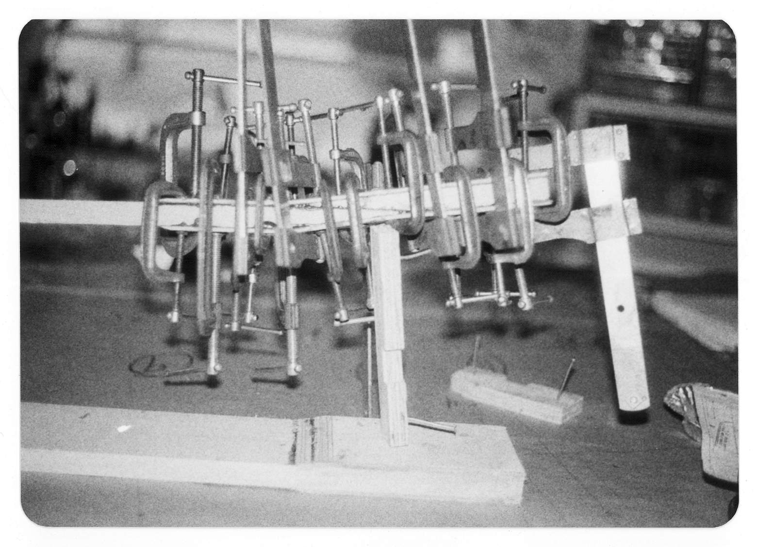
 On to the Right Hand Upper wing.  The leading edge strip of wood is glued and clamped to the leading edge ribs.

The drag wires are in and the woodwork is done except for the plywood on the top and bottom of the root ribs

 One panel remains to build.
 The last wing panel is the Lower Right.  Again the dog legged rear spar.

 One of the nice things about the Fly Baby is that it's like building a large balsa wood model.  There are some extra parts but the concept isn't so foreign to anyone who has built balsa models.


You can see the plywood cover on the wing walk.


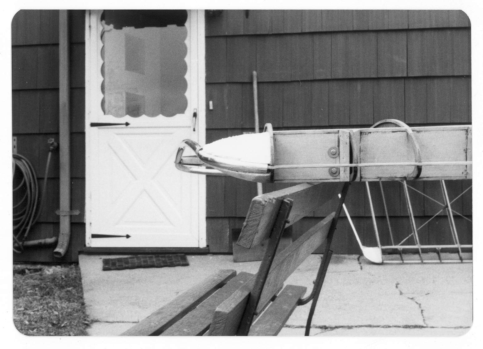
 Wing Tip Bow & Aileron.  The ailerons are just a front spar, ribs and trailing edge, pretty simple.

 The leading edge at the tip is reinforced with Styro-Foam.  It's glued in and shaped with a rasp and sand paper.

 All the wood work gets protected with 2 coats of varnish.  I like the smell of real varnish.  I guess it brings back memories of building Fly Baby.  I think these pictures were taken 24 April 1975.  That was the day the FAA signed off the wings for cover.  The aluminum leading edge couldn't be installed until they had inspected the structure.

Left Hand Upper.


 Center Section.


Strut and wire fittings on the bottom of the center section.


 Right Hand Upper

Right Hand Upper Tip.

  Left Hand Lower.

Time to build the struts.

On April 24, 1975 the FAA signed off the wings for covering.