In order to get the fuel outlet fitting pointed in the correct direction and properly tight, I needed to tap the outlet fitting about 3/4 of a turn deeper. This left some metal shavings in the tank so I had to open the access to get it all out. Removing the RTV was a pain. In the old tank I used a cork gasket 1/8" thick. I decided to use the same material on the assumption it would be easier to cut loose if I need to get back in again. This also meant another leak test.
I decided I would rather support the tank with some straps since I had used a weaker aluminum to make the tank. Because of the sump I needed the straps at the outer edges. To make sure they couldn't move off the tank I decided to make them from one piece of aluminum with some lightening holes. I used 2024-T3 aluminum 0.032" thick. With the main straps 2" wide they have the same cross section area as a piece 1/4" square. The aluminum has a yield strength of 50,000 psi so each strap can hold over 3000 pounds.
I made a pattern from card stock and used it to make the support strap blank.
The pattern was fitted to the tank and the fuselage so I could use the bolts which hold the support blocks to attach this strap and eventually the top straps.
The finished pattern ready to transfer the shape to the aluminum sheet.
For the curved corners on the bottom sides of the tank I used the Shop Smith tubes again. The strap was clamped on and bent down with a block of wood and a mallet.
They fit nicely in the corners.
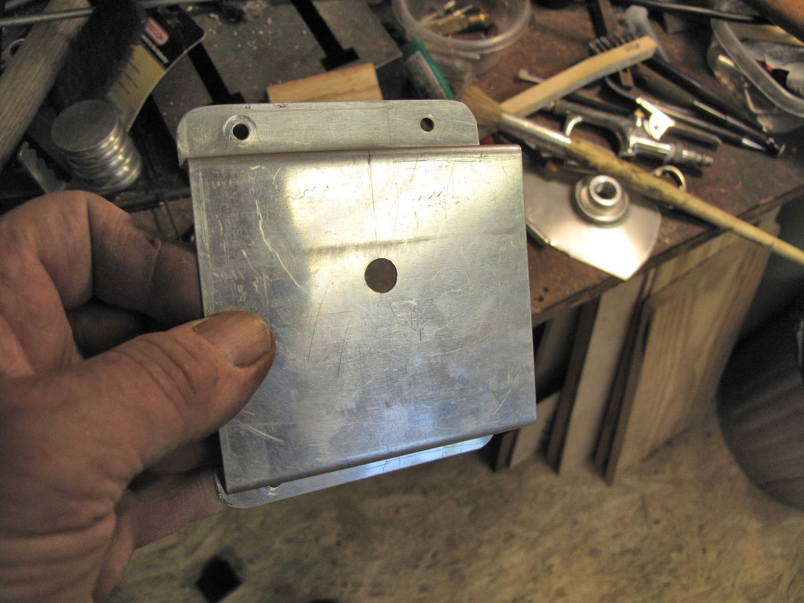
With the ends bent I added a flange around the sump opening so there would not be a sharp edge touching the tank and potentially causing a crack in the tank.
I glued some felt to the strap to prevent chaffing.
The corner on the first side was bent to fit on the top longeron The bolt holes were punched and the strap bolted in position.
I wanted to position the bend, on the other side of the fuselage, so the tank would set on the strap, not on the ends of the tank. I put some rubber spacers on the corners above the support blocks to lift the tank slightly, then strapped the tank back down.
I pulled the strap tight and marked the bend. It turns out I didn't get it tight and had to add some stiff felt under the tank to lift the it slightly off the support blocks. I probably would have done better to use the bend lines from my pattern. In the end it all fits well.
To mark the bolt holes I used a ratchet strap to hold the support strap down tight and center punched the holes from inside the fuselage with a duplicating punch.
For the top, hold down, straps I reused the idea and the bearing blocks form the old tank straps.
I cut 1 1/2" wide strips of 0.032" 2024-T3 aluminum. I don't have a 4' wide shear so I used the straight edge and Plexiglas cutter like I did for the
cowling panels. I wanted the joint on the straps to be on the side of the fuselage, however 48" didn't give me enough length to fold the end over for the bearing block. To solve this I made separate pieces riveted onto the long straps.
I bolted the strap piece onto the bearing block and formed the bend around it.
With the strap end and block clamped in the vice I used the sheet metal pliers to form the bends so the bolt is in line with the strap.
I used the same process to make the short ends of the straps.
I used one of the end pieces, before I bent it, as a pattern to layout the rivet holes on the long straps. I held them on edge to align them while punching the rivet holes.
Once the holes were punched the end was trimmed to length.
Before riveting everything together I did one more fit check on the fuselage.
All the aluminum pieces were Alodined and then riveted together.
The straps were bolted in place and the tank pulled down tight with a ratchet strap.
I found a problem when I went to tighten connector bolts. I made the openings 5/8" wide and the bearing blocks from 1/2" rod. It was very hard to get the wrench on or off the nuts and bolts. I should have made the opening 11/16" wide and the bearings from 5/8" or even 3/4" rod. In the end I got the bolts tight.
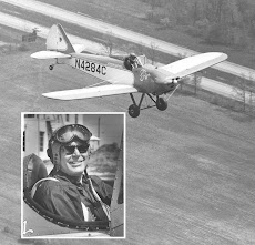
The gas line is installed. When I get the last things hooked up on the engine I can run the engine.
I like the result.