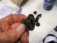
The gasket set, from Fresno Airparts Co., included new engine mount rubber cones, so I decided to replace the old ones. This was much easier to do with the weight of the cylinder off the engine.
I suspended the engine with a ratchet strap so it would not accidentally fall and ruin things. I snugged it tight but didn't use it to move the engine like I did with the come along in the attic. I loosened all the nuts leaving them so a few threads held them on. This gave some wiggle room for removing the old rubbers. I did the upper 2 mounts first. The bolts were driven almost out with wood blocks. Then the engine was tipped down just enough to get the back rubbers out and the new ones on the ends of the bolts.
To get the lower ones out the nuts were put back on the new top mounts and the engine lifted slightly at the prop shaft.
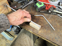
The bolts are a tight fit in the rubbers so I used a large C-clamp to push the bolt through the rear rubber. It was a little awkward but it worked fine. I used a hardwood block to protect the engine mount casting. The bolt stops at the block but a quick tap with a plastic mallet finished pushing it forward.
Make sure to clean the bolt threads so the nuts will tighten to the proper torque. Mine had oil and old rubber in the threads.
A rubber mallet pushed the front rubber onto the bolt far enough to get the nut started.
The engine book says the nuts should be tightened between 60 and 80 inch pounds. I used 70 Inch pounds so I could adjust the nut slightly, either way, to align the cotter pin hole.
The old ones were in various states from very good to this badly cracked one. Definitely worth a couple hours work and good fun. Just like real airplane mechanic work. Oh Yeah, I am a mechanic.
Tuesday, December 19, 2017
Wednesday, November 29, 2017
Engine Cylinders Removed For Inspection
Because the engine has been setting for 23 years I have been concerned the cylinders might have some rust. Until we moved the plane to the tent, the engine has always been in a dry indoors space. I decide the only rational thing was to remove the cylinders to have a look. It would also be a good chance to replace the rubber seals on the induction system.
Today was a beautiful sunny 66 degrees so I quit working and spent the afternoon removing the cylinders. The cylinder baffles were removed, then the intake tubes.
It really didn't take long.
The first cylinder is off.
The good news is, there is only a little rust at the upper end of the cylinder barrel in the combustion chamber, not where the rings ride. I'll clean up the rust so it can't come loose and get into the oil.
With all the cylinders off the inside of the engine looks really good. It should since I only have about 125 hours since I overhauled it. The connecting rods are protected with chunks the foam noodles the grand kids pay with in the lake. I'm eager to get the cylinders cleaned up, everything well oiled and back together.
A very worthwhile project.
Monday, November 27, 2017
Wing To Fuselage Pitot Static Lines
The last thing needed to hook up the Pitot and Static lines is to connect the aluminum tubing in the wing to the Nylon tubing in the fuselage. It turns out there don't seem to be any ready made connectors for joining these different materials.
I decided the solution was to do this like the connections at the Pitot Static Head using a piece of soft rubber hose. Before making each piece of tubing a bead was crimped to each piece of tubing. Then the appropriate nut and ferrule were installed on each end.
The hose was safety wired as before.
The aluminum tube for the static line was made a little longer so the hose would be clear of the nose rib hiding between the bulkhead fittings and the root rib. The lines end about an inch inside the fuselage. They're attached to elbows in the fuselage and will be joined to the wing when the wings are installed.
Sunday, November 26, 2017
New Pitot Static Probe
The Pitot Static probe on the Fly Baby Biplane is mounted about 2/3 of the way up the left wing strut. It's a home made probe similar to this factory one I saw at Oshkosh. Our old one was made with fairly light aluminum for the mounting braces and screwed to the strut. The light braces have been bent several times and just like on the landing gear water has gotten into the screw holes. I decided I needed to make a new one of sturdier aluminum, that clamps to the strut, more like the factory probe.
The old one worked so the original idea was to just make a new mount for it.
As I disassembled it I realized I probably should just make a new one using some of the same concepts. The old one was taped and safety wired together.
The tube connectors are pieces of 1/4" I.D. brass tubing which was splitting.
The probe tubes are separated by a piece of wood, which I liked.
The static probe was A piece of 1/4" aluminum tubing with the end hammered closed in a bullet shape, with a pattern of air holes. To make a new one I used an Oak block to support the tube while rotating it and slowly hammered the end closed. The tube wanted to slide along the block as I hammered so I leaned a piece of wood against my vise as a stop. It worked fine.
The last, tiny bit of closing was done by hammering straight down on the end.
It was fairly smooth but I decided to lightly file off any slight bumps. I aligned the tube at an angle with the cutting edges on a smooth mill file. By gently holding the end of the tube between my fingers I was able to rotate the tube and nicely clean up the hammer marks.
It was easier to form this end than I thought it would be.
I prick punched a pattern of holes, 1/4" on centers, 3 holes on the 4 quadrants and 2 hole between each set of 3.
The smallest drill I have is 3/64". The only chuck I have that will hold a drill this small is the little chuck on my angle drive. I had just gotten this chuck a couple weeks before so it was my first chance to use it. It worked out very well.
The hard part was deburring the holes. I used a piece of 3/32" welding rod to work the burrs until I was sure I had removed them all. It was mostly a matter of knocking them off or having them close the hole and then poke the hole clear until they all fell off.
The tube was bent so it would be parallel to the bottom of the upper wing, same as the old one. The joggle in the tube is to allow a piece of soft rubber tubing as the connector. I thought about using AN tube fittings but I wasn't sure I could make both tubes fit perfectly.
The Pitot Tube was formed like the old one but with a joggle to the side so the connector tubes would clear each other. I also made it longer so the connector hoses wouldn't be beside each other.
For the block of wood separating the tubes I used a scrap piece of 1/4" spruce. I used an Exacto Knife to carve notches for the tubes along the edges. I also rounded the leading edge to be streamlined. I just couldn't leave it square.
To help the connector hoses seal I crimped a bead on the end of the tubes using a hardware store compression fitting. They sell extra rings so you only need one fitting. You need to drill out the hole in the nut so it will slip over the bends in the tubes or you'll have it stuck on the tube. You could put the bead on before bending, but I find it easier to bend and then cut the tube to length.
I also Alodined the tubes to give them a little corrosion protection. I like the Gold Alodine better than clear for these things because I can see it working to judge when it's done.
To hold the tubes in position while I made the remaining parts I glued them and the wood block together with some 5 minute epoxy. I used a piece of non-stick aluminum foil to wrap everything. This minimized any trimming of excess glue and held the parts in position while the glue set.
The next piece was the strap which clamps the tubes to the strut. I worked out the shape with a piece of card stock. The aluminum is 0.032" 2024-T3.
After Folding it in half, so it would fit snug to the tubes, I Clamped it in the vise with a piece of 1/4" rod. The piece of Oak has a 1/8" radius on the corner to make the bends to fit the front of the strut.
Back in the vise with a piece of 7/8" tubing to from the sides to the strut leading edge radius.
It makes a nice fit to the strut.
These pieces will replace the fragile side braces with some more 0.032" aluminum. To help hold the tubes from coming loose in flight, I rolled the edge over to make a "J" shaped piece. The length of the "J" section is less on the piece which hooks around the bottom than it is for the piece around the top.
The "J" shape fits snugly to the tube.
To form the hook edge I pounded the aluminum around a 1/4" rod to make a 90 degree bend. Then I clamped the short end in the vise and continued to increase the bend in small increments until I had a 180 degree bend. For each added bend you have to loosen the vise and rotate the part a little than hammer a few more degrees of bend with the wood block. It works just be patient.
The aft ends were bent out, like on the clamp strap.
Then the second bend was marked to fit the strap.
The second bend was made to those marks using the piece of 7/8" tubing. These side braces will get riveted to the strap to stiffen it all.
I trimmed up the braces, Alodined them, and glued them to the tube assembly.
The strap was glued and clamped in position before drilling the rivet holes.
I wanted the probe clamped to the strut without screws and with the ability to tighten the strap so the probe pointed straight forward. For this I needs some little angle brackets on the sides of the strap, and also on a strap around the back of the strut. This way I can pull the strap tight and adjust the screw on each side to pull the probe left or right as needed.
The brackets are made form some scraps of 1/8" x 1" 6061-T6 aluminum angle. I drew cut lines and punched all the rivet and screw holes before cutting.
I didn't cut the parts off until I cleaned up one edge on the belt sander. It's much easier to hold the stick than the little parts, which easily get very hot while grinding.
After grinding the first side, the part was cut off, the second side ground, the next part on the stick ground, etc.
When I Fit the first bracket on the strap, I realized the bracket on the back strap needed the screw hole 0.032" further from base because there is only 1 layer of aluminum vs 2 on the front strap. Normally I make drawings to avoid remaking parts, but this was one of those figure it out as you go projects.
I needed to use flush rivets from the inside of the strap so I dimpled the aluminum and countersunk the bracket holes. The dimpling would have been better with all the pieces apart but the front rivets had to be in place to hold the pieces tight enough.
The front half of the probe almost done. I added a screw through the side braces and the block of wood to assure nothing comes apart in flight.
When I made the rear strap I realized I needed the front strap cut off at the back of the brackets to leave some gap for adjustment.
The finished probe. I added a small piece of aluminum tape in front of the static holes. I had done this on the old one to give a little turbulent flow past the holes.
Temporarily in position on the struts to make the tubes which connect the probe to the tubes in the wing.
The tubes were formed, and Alodined.
To secure them to the struts I lashed them on with cotton cord like I did on the landing gear legs.
3 coats of varnish fills the cords and glues them to the struts.
I filled the old screw holes and varnished over them.
To keep the probe from moving, I applied friction tape under the strap pieces.
To hold the Connector hose to the tubes, and assure a good seal, I wrapped them with safety wire on both sides of the bead.
I found it best to start at the free end of each to to assure I was close to the bead and still on the end of the aluminum tube. I snugged the twisting just tight enough to slightly squeeze the rubber.
A few twists are enough to get to the other side of the bead and repeat the snug twisting.
The ends of the safety wire, as always, are folded over to help prevent injury on the sharp end.
I probably could have made the end of the Pitot Tube a little longer since the rubber tubes overlap slightly, the mistakes of not having a drawing.
In the end I like it. It's solid. There are no screw holes in the strut and I can adjust right or left if needed. I also like the Industrial look, very cool.
Subscribe to:
Posts (Atom)


