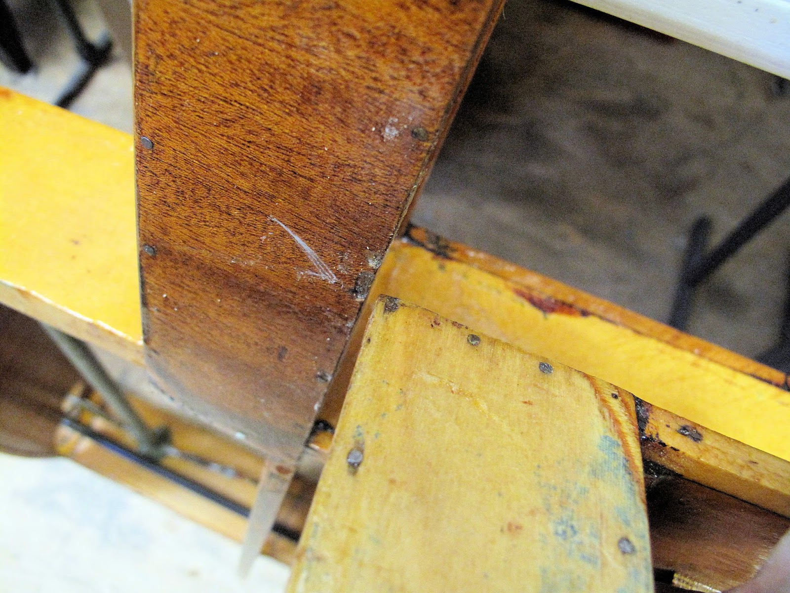
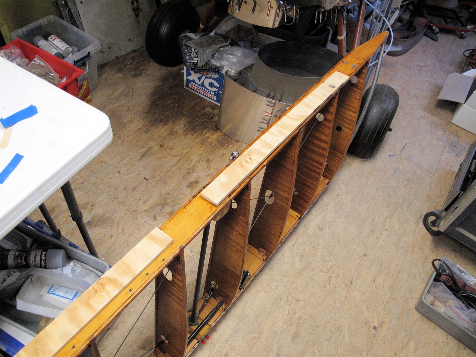
The wing tip bow is made from a piece of 3/4" aluminum tubing. A piece of the tube continues on the aileron to the aluminum trailing edge. On the right aileron this tube had come loose. Nothing was broken but the tube wiggled badly. At the end of the spar it was attached with an aluminum strap riveted to the tube and nailed to the strut. I assume it got hit by something and just loosened the nails enough to wiggle.
I decided to make a larger corner gusset which could be screwed to the spar. I made a card stock pattern to work out the shape.
The pattern was transferred to a piece of aluminum which was cut out and bent to fit.
I screwed it to the spar with a flat head machine screw with the nut behind the spar. The loose ends of the gusset were riveted to the tube and the covered with aluminum tape.
The strap on the left aileron was tight so I did not change it.
At the trailing edge the tube was split and flattened to fit into the trailing edge. This was all wrapped with duct tape. It seemed tight but I decided to remove the tape and rivet the trailing edge to the tube.
I spread the flattened tube open to match the shape of the trailing edge so there would be room for the ends of the Pop Rivets. On the left aileron I used 3 (1/8") rivets on the top and 2 between them on the bottom. There was about a 1/4" mismatch between the trailing edge of the 2 pieces. I formed a a piece from some 0.016" aluminum to blend the 2 pieces more evenly.
On the right aileron there was more of an overlap between the 2 pieces so I used 3/32" Pop rivets, 5 on top and 4 between them on the bottom.
There was less mismatch between the 2 pieces so I ground the end of the trailing edge piece to blend it to the tube.
The finished joint was covered with aluminum tape.
I sandblasted and repainted the control horns, then reinstalled them with new hardware. I rounded the corners. Square corners are extra little bits of weight with no extra strength. I tend to get cuts and bruises from them so I prefer round corners. Inside corners like on this horn need to be round to prevent cracks from stress concentrations. I used a 1/4" chainsaw file to round this corner.
The aileron hinges were attached to the wing rear spar with 8-32 machine screws and nut plates on the front of the spar so you could cover the wing and then attach the hinges. The hinges on the aileron were attached with 3/16" AN bolts wood washers and nut. The hinges were install as the fabric was applied. You couldn't remove the hinges until the fabric was cut open. I decided to make some aluminum strips with nut plates riveted to them and then screw the strips to the plywood doubler.
After making the blank strips I located and punched the first hole. With a bolt in the first hole the strip was clamped in position on the aileron.
Using a 3/16" duplicating punch the other 2 holes were center punched on the strip.
A template was made from a piece of 24 gauge galvanized steel for the hole pattern of the nut plates. I keep a supply of the steel for making templates. It's cheap, easy to work, and holds up well in use.
Using a bolt to locate the screw hole, the template was held on the strip and the first rivet hole punched.
The template was then clecoed in position so the second hole could be punched in the correct location. It sounds slow but with 30 rivet holes it's actually quick and accurate.
Two holes were added for the #4 screws to hold the strip to the aileron.
With the holes all punched each strip was held in position with 3 bolts in the screw holes. The rivet holes were center punched in the doubler. We need to drill a tiny clearance for the heads of the rivets. I could have used flat head rivets but then you need to dimple the holes in the aluminum and the nut plates are more expensive. I also have a box of 3/32" Pop rivets.
The mounting screws were started in the wood just enough so the screws would be correctly located while the bolts held the 3 screw holes correctly positioned. They were then removed to rivet on the nut plates.
You don't need much clearance for the rivet heads so a regular twist bit will work fine, very shallow.
A few of the strips had to be cut to fit around obstructions.
With the nut plates installed it's time to solve the problem of the aileron rubbing on the wing opening.
With a little experimenting I found I needed a 7/16" gap at the spar end in order to have about a 1/8" gap when the aileron moved past the wing. A piece of 3/8" aluminum and a piece of 1/16" plywood made a simple gauge.
To align the hinges so the hinge pins would be in a line I made some blocks of plywood. I made them wide enough so the bottom edge aligned with the bottom of the rear spar and the top provided a ledge for the hinges to set against.
I made 2 blocks and counterbored one to clear the compression strut bolts and washers.
I lined up the 2 blocks with a 4 ft. straight edge and lightly clamped them to the rear spar.
Pieces of 1 1/2" hinge stock were cut to length splitting the loop on each end so both end loops are on the same hinge half. This way the ends can be peened over slightly to trap the hinge pin. If the pin gets stuck doing the peening it's only stuck in one half of the hinge and the other half still moves freely on the pin. This is how the flap hinges are made on the Cessna 140.
If I were doing this from scratch I would start by making a template for the screw holes and using it to punch the holes in the hinges, then transfer them to the wood. In this case the holes are already in the wood. I've marked some blue ink on the bottom of the hinges around the area of each hole. Because the nut plates are already on the wing spar I can't use a 3/16" duplicating punch to center punch the holes. Instead I'm using a 1/8" punch pushed up through the holes to draw a small circle in the blue ink.
While holding the hinge down and tight to the alignment block you push up on the punch and swing the bottom end.
It draws a 1/16" circle in the blue ink.
With a little care the automatic prick punch can be located in the center of the circle to leave a punch mark for locating the Whitney punch.
The holes line up well within the tolerance need for a #8 screw in a 3/16" hole.
That all depends on paying attention to what you are doing. I wasn't even close on the hole on this hinge with a cut out for the washer. The good news is I needed to move the washer hole so it would be centered on a segment anyway, 2 mistakes in one part. Clearly I needed more caffeine.
With all the holes punched in the spar side of the hinges it's time to make the pins and assemble the hinges.
I cut the pins 1/8" shorter than the hinges. Each end was ground square and then spun to put a chamfer on the edge.
The hinges are mated with their other half. I stamped a code on each half to identify which position it was in, on which wing and which half was on the spar or aileron. I didn't assume the hole locations were interchangeable and I didn't want to have to sort out what went where.
The pin is about 1/16" from the end. The hinge was set on a solid surface and the end lightly struck at an angle to slightly peen over the end.
The pins are trapped but you could open the end if you had to.
Before removing the locating blocks the hinges are all screwed snug.
The hole areas for the aileron screws were blued on the hinges.
With the 7/16" block installed to provide end clearance the aileron is lightly clamped in position.
Again the holes were marked on the hinges, and the holes punched.
With the hinges installed we have all their pins in a line and the needed clearance at the inboard end.
I'll have to be careful applying fabric so I don't loose all this gap to layers of fabric. I have a plan for the fabric work.
The outboard end of the aileron moved out about 3/16". I don't plan to stress over it.