I've been slowly working on the sticky valve problem.


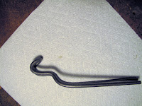
I cut a piece I thought was long enough, folded it in half and started forming the bends.
 The hooked end goes under the rocker arm shaft.

The step down is to push on the center of the spring retainer.
The wide gap is to have room to get the 2 keepers in or out.

 With the end hooked under the rocker shaft the tool is pressing on the spring retainer. To keep the valve from moving as you press down, the valves are resting on the flat top of this wooded block.


The block is made from a piece of 1/2" plywood for the base with a piece of 4x4 screwed to it. The 4x4 has the corners rounded, to fit in the barrel of the cylinder. The angles at the top allow the cylinder to set down so the valves are on the top of the wood. It works real good. I got the idea from an old training movie.
You press down on the handle to expose the 2 keepers. I use a good magnet to remove the keepers while pushing on the handle.


 I took the new valve and stuck it in the guide from the top to see how far in it went before sticking. It stopped about 1/4" from the bottom of the guide. It should have fallen all the way down. The build up of carbon stopped it.
 I didn't want to use a power tool because I didn't want to accidentally make the inside diameter too large and then have to get the guide replaced. It's a 7/16" diameter hole.


I tried a variety of 1/2" brass and steel brushes. The brass did nothing. The steel brushes worked, but very slowly. I also made a stick of 3/8" dowl to hold Crocus Cloth for final polishing.
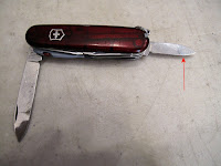
The thing that worked best was the small blade on my Swiss Army knife. Stick the blade in the hole, from the cylinder end, the curve of the blade prevents scratching the wall of the guide. Use it ase a screaper to scape the carbon as you rotate the cylinder around the blade. It's still very slow, but better than the wire brush. I used the brush after scaping with the knife. It was surprising how much carbon came loose as a fine powder.



I also tried Easy-Off oven cleaner. It worked well to soften the carbon on the valve stem where you could spray a good coating and let it set over night.
I used a Q-tip to apply it in the guide but really never got enough to do much.
It might have worked if I could have blocked the end of the guide and filled it with cleaner.

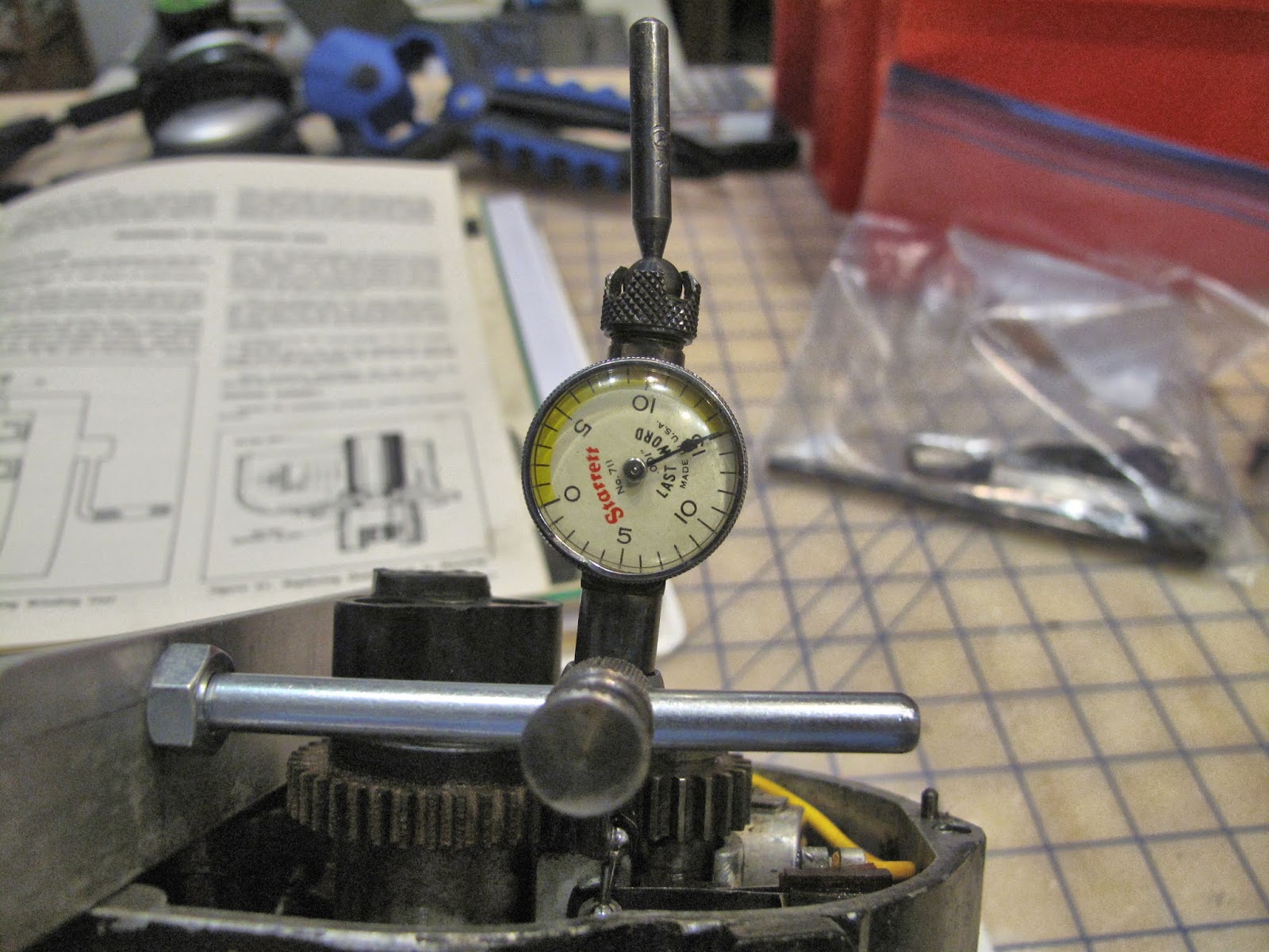
To make sure I removed enough carbon without increasing the hole size, I measured the outside diameter of the valve stem and the inside diameter of the guide. The book allows 0.0035" to 0.0055" clearance. The stem is easy to measure. The guide hole rquires a hole gauge, which you adjust to fit the hole, then you measure across the gauge. I had to work from the top of the guide so the longer hole gauge was able to reach the bottom. The anvils are spring loaded. When you have it where you want you twist the handle to lock it, then pull it out and measure it, Very tedious. There was so little wear that the best I could do was get the clearnace to 0.0035". The valve really moves freely when you have that clearance.


Carefully reinstall the valve in the guide so you don't wipe off the grit or get it on anything but the valve seat.
You are going to oscillate the valve against the seat to lap the 2 to the same angle for a tight fit. They make a stick with a suction cup on the end to do this but it takes a very long one to reach down into the cylinder. Instead I used the drill chuck from the ShopSmith to grip the end of the valve stem and pull the valve against the seat vs pushing it with a stick.

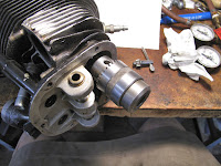
 The lapping process is simple. With the valve tight to the seat you rotate the valve back and forth about 40 degrees until you feel it moving smoothly. You really feel the grit at first. Then move the valve off the seat, rotate 90 dregees and repeat. Keep doing this in sets of 4 90 degree moves until you barely feel the coarse grit.


Clean everything well to be sure no grit is left to get where it shouldn't be, then pressure test the cylinder to assure you have a seal. Repeat the process if needed until it seals. They do make lapping compound as fine as 1,000 grit. I didn't order any.

 I didn't want to lubricate everything, put the piston back in and reinstall the cylinder on the motor just to leak ckeck it. Instead I made up a plate to seal the bottom of the cylinder. I used some scrap 1/8" steel, some 3/8" nuts and bolts from Tractor Supply, and some 1/8" cork gasket material glued to the steel plate.


Snug the bolts up and it seals, so you can use the cylinder differential pressure tester to slowly apply pressure. Yea no leak.


 There was no logic by which I can believe this was the only cylinder with carbon built up in the exhaust valve guide. I couldn't in good conscience put this one back on and ignore the others. Off with the next cylinder and repeat the process.

 When putting cylinder 4 back on I couldn't get the hydraulic valve lifter to compress to get the shaft back through the rocker arm. I called my friend Caleb Glick, who has since died and will be sorely missed. He explained that the check ball in the plunger was stuck and that the plunger can be removed with a magnet, then cleaned. This involved removing the casting which has tabs cast in it to prevent the plunger falling out of the lifter.


Once the casting was off the plungers are easy to remove with a magnet.

 The long piece on the left has the check valve in it. It lets oil flow through the lifter and up the push rod to lubricate the rocker and valve. I blew Brake kleaner in the small tube untill it was cleary open, then I oiled everything and put it all back together.
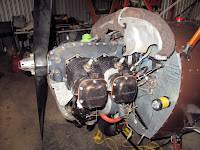 I found one of the lifters on cylinder 2 was not compressing so I took the cylinder back off and cleaned the check valve on it. All 8 lifters are now working fine.


Cylinders 2 and 4 are on, and 1 and 3 are off to clean the valve guides.
Cylinder 3 was easy, but I replaced the valve on cylinder 1. Even though it hadn't stuck it was worse than cylinder 2. It took more force to pound out the valve.

 After the first lapping the valve had some leakage. I blued the sealing surface on the new and old valves, installed them with no compound, and only oscillated it a few degrees. There was a small low spot on the seat which needed some more lapping.


I could hear a very slight leak even though the pressure was good. I put a few drops of soap solution on top of the valve. You can see the bubbles all the way around the valve at 10 psi. More lapping.

 With the valves working the cylinders are back on and pressure checked just to be sure, all 4 were good.


One side at a time the exhast and baffles went back on and everything was reconnected and safetied.


 When I finished today I just need to clean up the mess, do one more inspection, and reinstall the cowl sheet metal, we're getting there.