Friday, April 1, 2016

Cabin Heat Box

I may have told this story, one day I decided to go flying when it was 15 degrees on the ground.  I had on my snowmobile suit and other warm cloths, and I've hang glided when it was 2 degrees out and snowing.  It never occurred to me how quickly I would get cold.  After 15 minutes I was shaking so badly I wasn't sure I could get back to the airport or land if I did.  Right then I decided to add some cabin heat.  It wouldn't have to make the cockpit warm but if it raised the temp. even 15 to 20 degrees it would help.  I've since read a book where they were teaching people to fly on Lake Fenton, where my wife grew up in Michigan, in winter flying Curtiss Pusher knock-offs.  I have no idea how they survived it.  The interesting thing is that I have a WACO and one of the founders of WACO, Sam Junkin, was working at this company at that time.  I've read letters between him and Clayton Bruckner, another WACO founder, written while working there.  Small world.

One of the things needed to safely have cabin heat is a fireproof valve to turn the heat on or off and which will prevent flames getting into the cockpit if there is an engine fire.  The valve box gets mounted on the engine side of the firewall.  I'm using 20 gauge (0.035") 1018 steel to make the box because I have lots of scrap from making Curtiss OX-5 Exhaust Manifolds and elevator horns for the WACO NINE.  I made the box from one piece of steel with the sides welded together.  The holes are where the inlet and outlet tubes connect to the top and bottom of the box.  When the heat is off the hot air from the exhaust heat muff passes through the box and out the bottom of the engine cowl.  The tabs sticking up here are the corner flanges which will get welded to the sides when the box is folded.
The rings were made from strips of steel formed around a socket wrench and spot welded together.  I had to buy a cheap spot welder to make the exhaust manifolds.  It has been a useful tool.
If you look at the first picture I left about 1 metal thickness sticking up to use for the corner weld.  The corner is just melted together with the torch.

Before folding the weld scale was grit blasted off.  The tabs sticking up are the mounting flanges for the top and bottom of the box.  We'll form the other 2 mounting flanges after the box is folded.  I want all 4 flanges in a plane.  I'm good but not good enough to make all these bends and have the flanges actually line up.

The first bend was made over an oak form block with a small bend radius and a few degree spring back angle so the bend could be made square.  The piece of plywood is a backing block.  It's needed so the box wall will stay flat and the bend will be tight to the block.

The same process was used for the second bend.  We now have 2 sides of the box folded.


A form block was made to set in the box while forming up each end.  The top and bottom, sides with tubes had the mounting flange  and corner tabs formed before welding on the tubes.

The first 2 sides prevent over bending the top and bottom enough to get them to spring back to a square bend.  As a result they need to be held tight with clamps while spot welding the corner tabs.

A couple welds were made near the open end of the box.

The clamps were then removed and more welds added to each corner tab.

Now we need to form the last 2 mounting tabs so they all set tight to the firewall.


The form block was clamped to the side using the thickness of my thin steel scale (ruler) as a gauge to offset the block for the thickness of the flange.

The tab could then be hammed to  90 degrees and the mounting surface aligns with the top and bottom mounting flanges.

I always hammer metal using a block of hardwood, not shown, so the metal being hammered over won't get dented from the concentrated blows of the hammer.


We need a stop for the flapper valve so when it's open it can't get stuck.  This hat shaped piece gets welded into the front of the box.


With the basic box formed I clamped it to a piece of 3/4" plywood to hold it flat while I welded the corners shut.  It might not have warped but this seemed an easy precaution.
A steel hinge was welded into the box and the the valve (door) welded to the hinge.  A spot welder made all this so easy.
The closed (heat off) position.


When it's in the on position the valve sets tight to the stop and very little hot air will leak around the valve.


The box is test mounted to the firewall to work out the hole size and see that it works properly.

The eye bolt is to attach the control to operate the valve.


The box needs to be painted and the outlet tube riveted on.

We'll come back to this when I hook up the control to operate it.

Thursday, March 31, 2016

New Gascolator Bracket


 We have a perfectly functional Gascolator, but the bracket is assembled from several pieces and 2 bolts.  I like the glass bowl so you can see that the gas looks clean, and see if the water was all drained out.
It seemed I could easily make a lighter weight mounting bracket from a single piece of aluminum.  I know it's not much savings in weight but that attitude is how you get a plane 100 pounds over weight.

I started with a card stock pattern to see how it would all work.  I decided to reverse the clamp at the top because of where I wanted to mount it.


 With all the details worked out it was time to flatten the pattern and layout the blank on a piece of 0.040" 2024-T3 aluminum.  I could have traced the pattern but it really wasn't made that perfectly.  It was more just to work out ideas and get critical dimensions.

 The holes were punched and the cuts were made with a band saw so there would not be any distortion from trying to use snips.

Other than making sure there was an adequate radius in each bend the bends were not critical.  I left plenty of material for locating the mounting holes after it was all formed.

 I made up a pattern for the mounting holes using the old part and the holes in the firewall.

From the pattern the holes were punched in the mounting flanges.

 The finished part nicely replaces the old one.


 The wire bale which holds the gascolator together also hold it on the bracket.  It just needs to be screwed to the firewall.

Wednesday, March 30, 2016

2015 - Back to the Firewall

It's only been 7 years.  OK, I've been working a Cessna 140 project and a 1926 WACO NINE project while the Fly Baby sat collecting dust and filling up the attic.  I've realized the plane will be 50 years old in July 2016.  I need to get this back in the sky, and I need the attic space to assemble the wings for the WACO.  The Cessna long ago moved to a tent in the driveway but there is only so much room in the attic.
 I realized I needed to be able to easily move the engine out of my way and back as I work on the firewall.  I don't really have room for an engine hoist.  I have this old come-along to lift it with.  I screwed 4 eye bolts into the rafters to hold pipes for the come-along to hang from.  With caps on the end of the pipes they won't slide out of the bolts when moving the engine.  The hardware store had some nylon tube fittings which work great for bearings.  You have to lighten the load a bit for them to slide on the rough galvanized pipes, but it works to quickly move the engine to the firewall or out of the way.


 I did find it worked better if I balanced the engine with small ratchet straps at each end.  It was easier to align the engine mount with the bolts.

You can see the old holes in the wood former.  I wanted to use as many of them as possible rather than make more holes just to locate things a little better.

 Originally we stuffed several items through one hole and used putty to seal it.  I wanted a grommet on each item so I located more holes to make it all work.  I also wanted cabin heat so I needed holes for it.  I know it's open cockpit but a few degrees warmer can make a much nicer or longer winter flight.
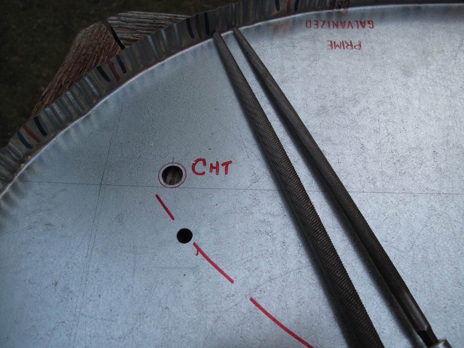
 All the hole where a grommet was used were drawn to show the hole and the outside of the grommet.  It helped me keep it clear what I was doing at each hole.  I also made notes of what was going through the hole because each grommet needed to be sized to fit tight to that item.

Holes were drilled as large as could easily be done and the filed to size with progressively larger files.  The holes were then deburred to protect the grommets.


 With all the holes done, the firewall goes back on the fuselage to mark the new holes needed.  The curved line is the bottom of the tank.  The rudder pedals were also marked to prevent locating things in bad locations.

 The new holes were cut in the wood and sanded.  All the bare wood was varnished.

The large washers on the engine mount bolts are to help keep the mount from compressing the plywood.

The firewall with grommets.  I plan to make metal covers to seal the grommets against fire, and do fire protection for the hoses.

Tuesday, March 29, 2016

2008 - New Firewall


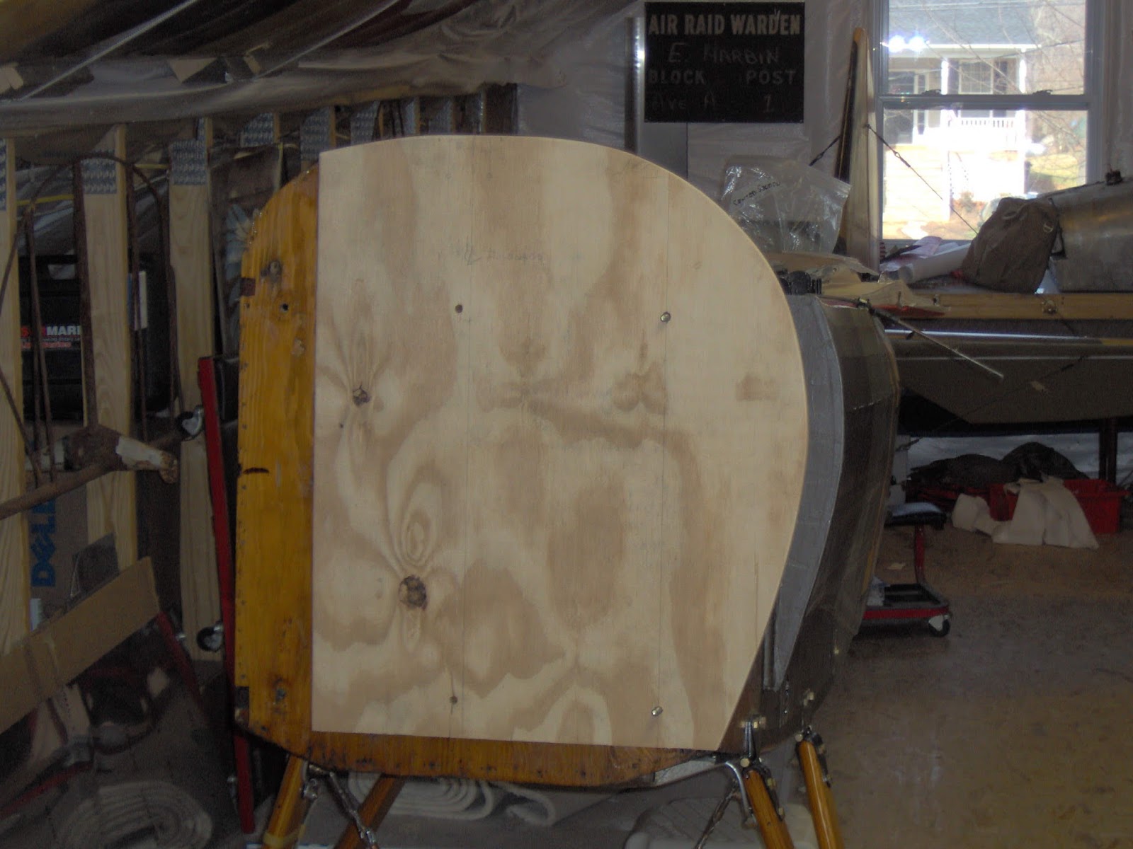
 Before we added the stingers to the fuselage it was 24' wide and flat on the sides.  You can see the firewall end of the fuselage here compared to the shape with the stringers.  We had a firewall which fit with the shape of the stringers.  The problem was that after years of changes it was riddled with holes.  The best solution seemed to be just to make a new one from 24 gauge galvanized steel.
 The firewall has a flange formed on the edge for the fasteners to screw the cowl together.  I made a form block to bend the flange over.  As you can see it is not a full block.  The reason is I'm not planning to fully bend the flange to 90 degrees on the form block.  The flange is 1-1/4" and therefore needs a lot of flutes to take up all the slack in order to form it to 90 degrees around the curves.  Normally you would put an angle on the edge of the block to allow the metal to over bend, past 90 degrees, so it will spring back to the desired 90 degree bend.  In this case the edges are just 90 degrees with a small radius on the corners.  I'm just going to bend the flange to about 45 degrees and then finish the bends with a hand operated fluting tool.
 The first engine mount bolt hole was drilled in the blank sheet of steel.  With a bolt holding the blank to the fuselage the next hole was marked.  I like using a Portalign to hold the drill when I can't use a drill press.  The blank was then mounted with 2 bolts and the third hole marked, drilled, etc. for the fourth.  It's slow but minimizes location errors.

 With the holes drilled the form block was used to layout the cut lines, edge of tape.  To prevent cracks, 1/4" holes were punched in the corners of the cuts along the bottom.  The flange will bend forward and the bottom, which does not attach to the cowl, will bend aft.
 The flange was bent forward to about 45 degrees.  You can see the wrinkles developing

 Locations for the fasteners were marked.  I wanted flat spaces for the cowl fasteners.  The original firewall was fluted by machine all the way around.  It made attaching the fasteners more difficult.  Since I don't have a machine I can put flutes where I want them and leave some spaces flat.

You can make the flutes as deep as needed to pull out the slack and leave the flange at 90 degrees.

The bottom 2" flanges were just hammered back with a block of wood to get a smooth bend.

I still need to locate all the holes for cables, hoses, etc.  The holes for the cowl fasteners will be added as the new cowl panels are made.

Monday, March 28, 2016

2008 - New Instrument Panel


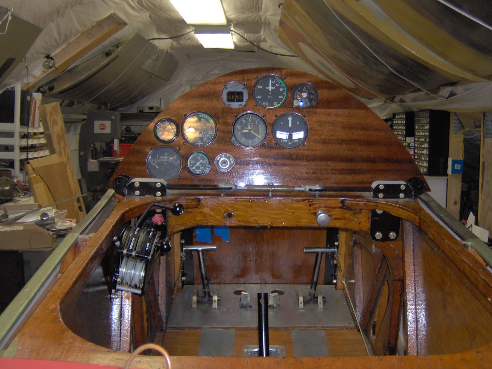
 The old radio still works but is no longer legal to use.  I also wanted a slightly different arrangement for the instruments.  The airspeed is top center with the compass and clock beside it.  This leaves room for the Altimiter and Turn/Bank neatly below them making a tight triangle of the most critical instruments.  They actually set a little higher this way and closer to your line of sight while landing.
 To the left are the engine instruments, near the throttle quadrant.  This leaves room for a future radio on the right.
I made a new aluminum panel from 0.063" 2024-T3 to get reasonable strength.  It's covered with an overlay from 1/16" mahogany plywood.  I stained it a little darker and varnished it.  I like the look.
 The old military surplus throttle quadrant was rebuilt.  I relabeled the mixture control for the fuel shutoff.  It had been done with a Dymo Labeler.  I also made a knob for it with a stack of rubberized washers.
The big change was a new mounting bracket tilting it and moving it up slightly to get some more knee room.  My knee always rested against the corner, now it clears nicely.


Sunday, March 27, 2016

2008 - Struts and Brakes

The landing gear axle and all the fittings were removed from the landing gear and wing struts.  The metal parts were sand blasted, Zinc Chromate primed and painted with Black enamel. The wooden struts were sanded to remove the old varnish and re-varnished with Marine Spar Varnish.  The fittings were then reinstalled with new hardware.

The landing gear was assembled and bolted back on the fuselage.  The landing gear bracing cables take a lot of abuse.  New 1/8" 1 x 19 cable replaced all the old.  I used the same method we used originally which was 2 Nicopress sleeves.  The first takes the structural loads.  The second just covers the loose end of the cable to prevent snags.  For the second sleeve have the cable installed and rigged tight.  Make the 3 crimps starting with the end toward the first sleeve and work down the cable

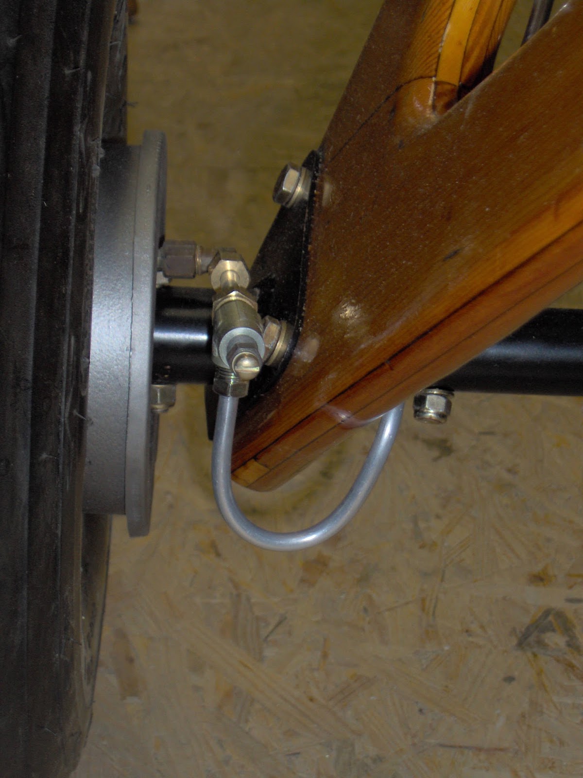
 Originally we ran the brake tubes along the front of the gear strut.  They really get beat up in front.  I decided to move them to the back and inboard corner of the struts.  That meant reversing all the fittings from the CUB brakes to turn aft.

I then routed the lines out of the bleeders and around the back of the struts.  There is no hose because the gear is rigid.

 I liked the use of cotton twine to hold the brake lines to the struts.  The twine was varnished after tying it tight.
 Because I'm working in my attic I wanted the gear easily removed.  A union was added in the fuselage where it wouldn't snag moving the fuselage down the steps.  From the union it's a short line to the CUB heal brake cylinder.