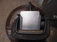
I wanted all the cables, wires, and hoses passing through the firewall to go through rubber grommets. The grommets seal each item so air and oil from the engine compartment do not easily pass into the cockpit. Because they are made of rubber they are not fire proof. A grommet shield is like a metal top hat which covers the grommet to protect it in case of a fire. Some like this one are simple covers made from one piece of galvanized steel. These work great for a wire to pass through before adding a connector on the end. For most things like the tachometer cable, the shield has to be made from 2 overlapping pieces since the nut on the end is so big the hole would never protect the grommet.
You can buy these but they are not cheap and they are easy to make from scrap metal. Because of the spacing of some holes in the old firewall I needed some non-standard ones anyway.
We need a punch to drive the top of the hat into the die. For the small (3/4" dia.) grommets I bought a short 3/4" bolt and sawed off the threads. You need to support the threads to get a clean square cut. a piece of 3/16" steel worked fine for this.
I also used a piece of 3/16" steel to support the bolt while grinding the end square on the belt sander.
I only need a small end of the bolt to make the pocket for the grommet so I used a stack of washers to give something to hold while hammering the bolt and to control how deep the packet would be. The bolt can be ground to whatever length needed. The pocket being a little extra deep won't hurt. The washers also help flatten the metal around the pocket, at the bottom of the stroke, since the sheet steel is not being clamped and it will wrinkle a little.
To put the radius on the corner of the punch (bolt) I used a rubber cup to hold it and a nut for a spacer. A socket wrench and magnet would have worked well also. You gust need to hold it while gently grinding a radius.
With the die made I could see it would move around in the washers making it hard to control centering the punch on the die (another washer). To fill the gap I put a piece of heat shrink tubing on the bolt. It did the job.
Using another washer for the die worked because the hole size was just big enough to provide clearance for the steel around the punch.
I ground a radius on the inside edge of the washer with the Dremel tool.
The strip of galvanized steel was placed over the die (washer) and the other washers stacked on top of the steel.
With the punch (bolt) in the stack of washers all the washers were aligned before hitting the bolt with a 6 lb. sledge hammer.
It made a nice pocket in the steel.
There are radii in the corners and the pocket is deep enough to allow room for the firewall to fit in the groove and for the grommet to be nicely protected.
I then made enough pockets for all the 3/4" grommets.
To center punch the location for the grommet hole I used a duplicating punch which fit snugly in the grommet.
I needed 2 mounting holes for each shield or shield half, if they were a 2 piece shield. For the first one I drew the locations and center punched the holes. The holes were then punched with the Whitney punch.
The piece was cut out and filed smooth. It became my master for punching the holes in the remaining shields.
The center hole varied in size to fit the hole of the grommet with a little clearance so whatever was passing through the grommet could not rub on the shield.
It would defeat much of the purpose of the grommet if it rubbed on the steel.
The mounting holes were than duplicated for the remaining pockets. The first hole was punched just holding the master snug in the pocket. A Cleco was installed and the second hole punched.
Blue felt marker was used to layout the area for the cut line. The master was Clecoed in place and the cut line scribed. The parts were cut with snips, the edges ground on the belt sander and then filed smooth.
Center holes were added.
For larger grommets a socket wrench was used as the die.
For the fuel hose and oil pressure hose a slightly different shield was made. The base was made by the same process from 20 gauge (0.035" mild steel).
A tube gets welded on to attach a fireproof sleeve over the hose. The tube was cut from a scrap of 0.035" 4130 steel tubing just large enough for the hose to easily pass through.
The tube was inserted in the base leaving about 1 metal thickness sticking out the back to make welding easier.
The tube was welded to the base on the grommet side. The assembly was grit blasted primed and painted.
Here are all the finished parts ready to install with their grommets.
You can see that the 2 piece shields are cut to leave plenty of overlap.
The shields are held to the firewall with sheet metal screws. I always start with the smallest crew which will hold so when the holes get worn you can go to a bigger screw size.
You can see how the hoses fit through the steel tubing.
The firewall is ready for the engine to bolt back on and the fire sleeves to be installed on the hoses.
A very neat professional job which will give a few minutes longer to get safely on the ground in case of a fire. With a wooden airframe and the fuel tank in your lap a few seconds could mean the difference between life or a horrible death. It was probably the thing WWI pilots feared the most, burning to death in their airplane.


