Tuesday, May 10, 2016

Lower Left Wing - Prep for Recovering


The lower left wing has had the most challenges.  When I disconnected the aileron push rod I found the aileron didn't swing up far enough to get the screws out of the hinges.  The problem has to do with all these 9 degree angles.  Ill fix this problem later.  For now I had to remove the cotter pins at each end of the 5 hinges and drive out the hinge pins. Then I could remove the screws and hinges to allow the fabric to be removed.
The hinges were numbered inboard (1) to outboard (5) so they can be matched up with their other halves on the aileron.


When I tried removing the bolts for the brace wire/strut fittings I found them even harder to remove then the right wing.  They are rusty but still structurally sound.  All that expanded rust just jammed them in.

I'll re-drill the bolt holes 1/32" oversize.
I found a couple drag cables with a lot of excess cable after the Nicopress sleeve.  I bent a scrap of 20 gauge mild steel to hang over the cable to protect it while I cut off the cable with the Dremel Tool cut off wheel.  The ends of the cables were again taped with friction tape and shellacked.


Were your eye protection it throws plenty of steel dust.

The pitot and static lines were made with nylon tubing.  It has worked fine but after 40 years it made no sense to trust it any longer.  I replace them with aluminum tubing.  To do this the leading edge had to be opened.  I decided to un-nail the inboard section along the underside of the wing.  This worked because it overlapped the outer section.  on the outer section I removed just enough nails to get the tubes loose from the ribs.
I color coded the new tubes and will mark which is pitot and which is static when I reassemble everything to make sure I get them hooked up correctly.  There was an access panel but I extended it a little to make it easier to tighten the fittings.
The nylon tubing was cable tied to the nose ribs.  I used the friction tape for the aluminum tubing.


At the inboard end I moved the connectors outboard a few inches, attached them to a floating bulkhead to make it easier to hold them while connecting them to the tubing from the fuselage.  I also added a small access panel.

The leading edge skins were nailed back on with nails 1/8" longer and any loose nails replaced.

The tie down ring on this wing also had a crack so I decided to make new ones, turned with the wind.  I bought some rings at the hardware store and sand blasted off the plating.  I ground just enough of a flat spot so the ring would stand on its own while welding.  I tacked both sides then torch welded them to the new plates.

After drilling the holes in the plates to match each wing I stamped them to make it easy to install them, "R" for right and "F" for forward end, etc.

After grit blasting, painting and baking they look good.


I forgot to take some pictures here.  The aft section of the outboard rib on the wing walk broke loose.  For some reason the aft portion of the cap strip on this rib was only about 3/16" thick so the groove where the rib web is glued in wasn't strong enough on the one rib which gets highly loaded when you step on the walk.  It's hard to step near the inboard rib.  I glued and clamped it all back together.  After the glue dried I cut a piece of 1/8" plywood to fit next to the rib web.  The idea was to glue in a piece which would allow another piece of 1/8" plywood to be glued to this piece and to the cap strips.  The forward end of these pieces were ground at an angle to fit the corner block.  It was all glued and clamped together.  After it dried the excess glue and plywood were trimmed to a nice fit.

When the wing is recovered I'll start the wing walk grit at the spar to help make sure this doesn't break again.

When the step sagged the trailing edge bent letting water puddle at the next rib and the end rotted off.

To fix it I cut a block of spruce the width of the cap strips to replace the end of the rib and made 1/16" plywood gussets for the sides, per CAM 18 (yeah I know it's been superseded).


All of it was fitted up glued and clamped together.  I've used T-88 glue for all the repairs despite my preference for Resorcinol, because there are gaps which fill better with T-88.


After the glue set up it was all sanded to a nice new rib end.
Rib 5 (root rib is 1) got damaged, probably while moving the wings over the past 20 years.  The lower cap strip and the 1/16" plywood web were damaged.  I cut a new piece of spruce cap strip with a 12:1 taper for the splices.  I used an Exacto saw to cut the 12:1 taper on the old cap strip and then carefully trimmed it from the plywood web.  Plywood gussets were made to cover the splices and everything was glued and clamped together.

Pieces of 1/16" plywood were glued to the sides of the broken web.  I used the Exacto saw to cut a split in each piece to get them over the wire without undoing it.  The slits are on the undamaged area and run at about a 30 degree angle, one forward and one aft.

All the repairs were varnished and as done on the other panels any wood that fabric touches was epoxy varnished.

 With the woodwork done I needed to replace the bent section of aluminum trailing edge.  The piece I ordered from Aircraft Spruce exactly matched the piece from 1975.  To flatten the areas where it fit over the ribs I clamped a dolly tightly in the vise and hammered the areas flat on the top and bottom.

 The ends had to fit over the plywood which was thicker than the ribs.  To open the radius at the trailing edge I used a piece of 1 1/2" x 1/8" steel angle with a piece of 0.032" aluminum wrapped around the edge.  You could probably use a small piece of the trailing edge material to cover the angle.

I slipped the trailing edge over it and squeezed it in the vice.  With it tight in the vise I used my fingers to fold the legs it back to a tight fit.


 You can see how much wider the radius is now.

It fit nicely onto the plywood.


 For reasons I can not guess the trailing edge of the ribs do not line up with the plywood at the step and the aileron cut out.  The nails hold the trailing edge on but can not take any load from the fabric pulling tight.  I put a blob of epoxy putty in the trailing edge at each rib and pushed the trailing edge onto the ribs so the putty was smashed around the end of each rib.  I can't imaging they will come loose or that the fabric will pull the trailing edge in.
 It's hard to get nails through the trailing edge material.  I used the automatic prick punch to put a weak spot for each nail to go through.

 The weak spots worked great.  All the nails went right through without bending.  I needed something solid to support the tip of each rib while pounding the nails.  I was going to cut a piece of 2x4 but I had this shovel handle I've been cutting up to make form tools, cheap source of round hardwood.  It was the perfect length and made nailing a cinch.

New trailing edge, straight and solid.  All the nails are covered with small pieces of aluminum tape.  In the Air Force we called it High Speed tape.  You could use it on the outside of a jet without coming loose.

I made the drain holes in the trailing edge larger than the holes in the wood to assure good drainage.


Monday, May 9, 2016

Lower Right Wing - Prep for Recovering


 The lower wings are a little more complex because they have the ailerons and the aileron controls.

The backing plate for the landing wires looks crooked but it's part of the complexity of the 9 degree sweep back of the wings.  The bolt pattern is perpendicular to the center line of the fuselage.

 Tie down rings were welded to the backing plate for the front strut fitting bolts.  You can see in the second picture a crack has developed along the edge of the weld.  The weld must not have had good penetration into the plate.  That is a pretty thick item to weld to a piece of 0.063" steel.  The ring is perpendicular to the airflow so I'll probably just make new ones turned 90 degrees.  We'll see after I get the one off the other wing.

 Taking the fabric off.

All the wood was in good shape.  The closest to a problem was a water mark on the bottom of the wood at the aileron cut out.  The wood is solid so it just needs a little more varnish.


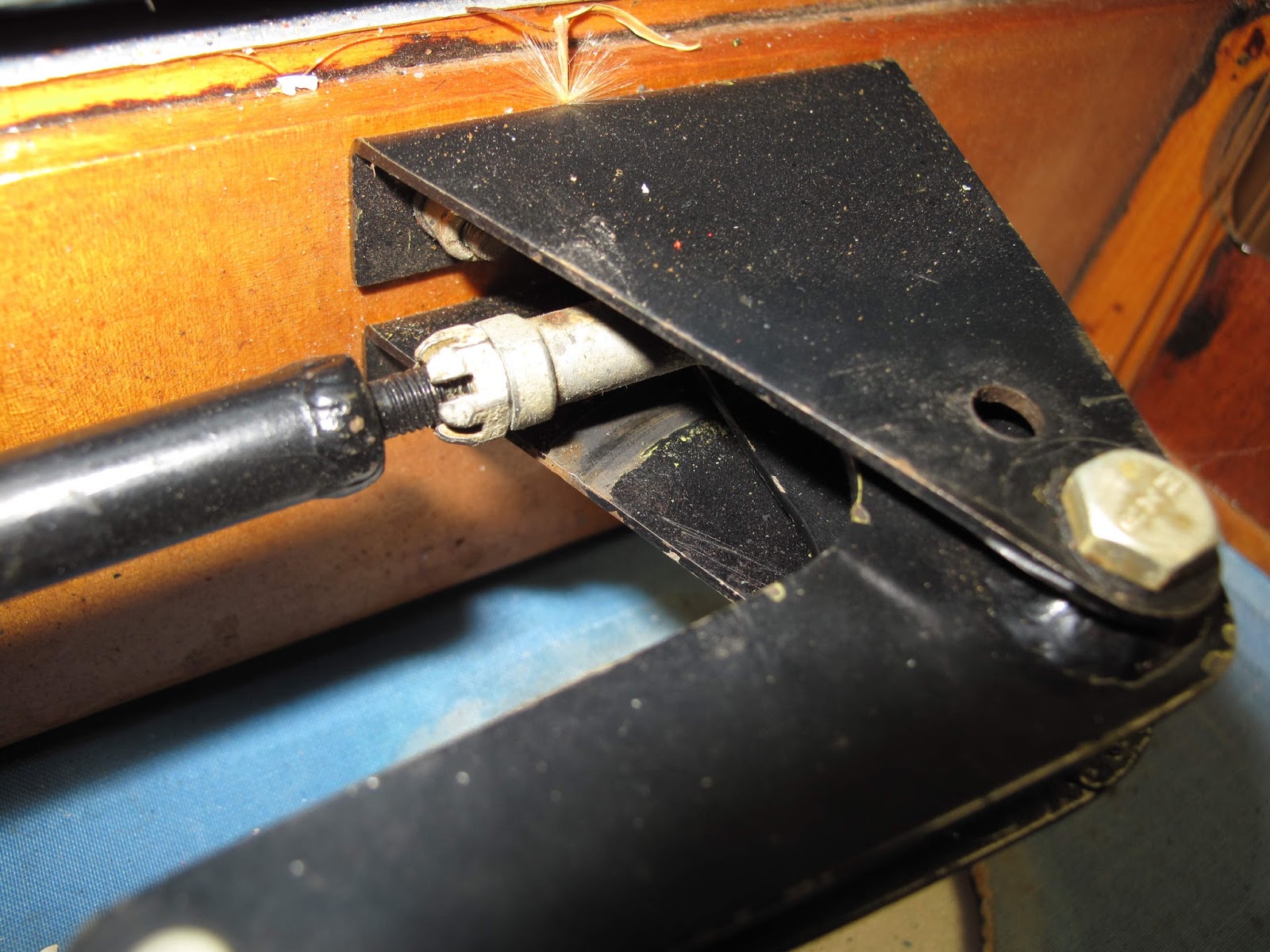
 One real problem I found was on the aileron push rod bell crank.  The lower end of the clevis pin on the long rod was rubbing on the bracket.  The aileron limited travel so that the pin was just at the edge of the bracket.  Had it moved off the bracket it could have hung up on the bracket.  That would have been too exciting if you were fighting a cross wind on landing and it snagged.

The solution was to move the brackets further apart to assure the pin could not touch the bracket and add washers on the pivot bolt to fill the gaps.
 To remove the brackets I needed access to the bolt heads on the front of the spar.  I decided to make a hole like I did on the center section for the Lewis Gun supports.  I figured one hole should give me access to both nuts.  Good plan but a little more careful examination of the leading edge or the plans would have shown me that like the center section there was a nose rib between the nuts and I really needed 2 holes.  I didn't do any damage so I expanded the hole to an oval.

 I thought about making new brackets but decided on a simpler solution.  I used a 3/16" chainsaw file to make oval holes.  I lengthened the holes 1/16".  This moved the brackets 1/8" further apart.  We've all seen slotted sheet metal holes.  In this case the loads on the bracket are light enough that there is no risk of the bracket pulling off the bolts.   My real concern was making sure the bracket didn't move back to the other end of the hole and cause the problem to return, not likely but why risk it.  I used the Whitney punch with a 3/16" punch to make some 1/4 moon shaped slugs from 0.063" aluminum.  The slugs fill in the hole to assure the bracket can't move.  The washers and nuts hold them in their holes.

 The lower bracket holes moved away from the vertical leg of the "L".  The upper bracket holes however moved closer to the radius in the corner of the bend.  I didn't want the sharp corner of the washer causing a possible crack in the bracket so I rounded one edge of the washers to fit nicely in the bend.

To make sure the rounded edge was where it belonged I put a black mark on the opposite edge which is visible while tightening the nuts.

 I made an aluminum cover formed to fit over the hole and taped it on with aluminum duct tape.

Other than the brackets the rest was just Epoxy Varnish to protect the varnish where the fabric touches wood.  I did replace any loose nails on the leading edge with nails 1/8" longer, as I did on the other panels.  I then used aluminum Duct tape over all the nails so they won't snag the fabric and to help assure they don't work out.  I used the tape on all the wing panels.  The adhesive lasts longer than regular duct tape and the aluminum should last as long as the leading and trailing edges.

It looks so fresh and new. It makes you want to get out the fabric and start covering.

Sunday, May 8, 2016

Upper Right Wing - Prep for Recovering


 The upper right wing proved to be in the best shape so far.  The process was about  the same as the center section.  All the fittings were tagged and removed.  The wing brace wire and strut fittings are held on with bolts which go the full depth of the spars.  We made the bolt holes a snug fit.  In hind sight I'd drill them 1/32" oversize to leave a slight gap.  Being a tight fit does not add any strength for these fittings.  The tight fit means that the least amount of rust causes the bolts to be almost impossible to remove.  There is always moisture in the wood so the bolts always rust.  I would also swab the holes with Linseed Oil to help stop the rust.

The pliers worked but I worried I'd break a bolt, they were that tight.


 With all the fittings removed I again started loosening the fabric at the wing root and then split it with a knife along the trailing edge and wing tip bow.

The wing was in really  good shape and only required cleaning and epoxy varnish where the new fabric will touch wood.

 You can really see the ringworm on the old dope.  If the colors had been dope instead of lacquer the dope could have been rejuvenated.  The rejuvenator makes the dope soft like new.  It will even fix ringworm or prevent it if used every 5 to 7 years.  You can see how sun light gets through the ringworm cracks to ruin the fabric.

Other than needing new fabric this wing was ready for service.

Saturday, May 7, 2016

Lewis Gun Mount on Center Section


 Some time after the plane flew with the biplane wings Dad built a fake Lewis gun and mounted it on the wing center section.  Rather than take the plane apart and uncover the center section he built a mount for it which could be bolted on to the assembled plane.  The tubes support the light weight gun.  The wires prevent the propwash pushing it back.  It works fine.


 I got to thinking that the tubes and wires are probably disturbing the air flow such that there is little or no lift from the center section.  As a result I decided that while I had the center section uncovered I'd make a different mount.  I have no interest in something as complicated as on the SE5 since the gun doesn't work.  I would like to make one that fires acetylene gas some day.

I decided to mount the gun to the spars with little "A" shaped mounts.  The forward mount picks up the old clamp around the barrel and the aft mount picks up the bolt hole in the gun, from the old mount.  As a result the idea is the same for both mounts but the forward mount is taller than the aft mount.

I bent the brackets with 30 degree and 60 degree bends.  to get the mount hole on each half the same height I made the hole in one, clamped them to the work bench, and punched the second hole.  Then the second can be cut to length and the end rounded like on the brace wire clips in the prior blog post.


The gun sets nice.  I made "L" shaped brackets for each side of the center rib.  They are riveted to a piece of aluminum using the rivets which hold the nut plates to the bottom of the supports.  The aluminum gives the brackets some stability and a place to attach the fabric covering.

The nut plates allow the mounts to be screwed on after covering.

The supports are the same, forward and aft, except the bend angle is slightly different because of the rib contour.


The supports are each bolted to the spar with a 3/16" bolt.  On the rear spar they go all the way through the trailing edge with a little counter bore so they don't show through the fabric covering.

For the forward spar 2 small holes were sawed into the aluminum leading edge to get to the nuts, and then covered with aluminum duct tap.

The finished mount should work fine and may even be slightly lighter, a nice bonus.