When I started I thought I could make a simple extension to the cooling baffle under the crankcase. There was no way to make it line up with the hole in the nose cowl.
After wasting an evening or 2 I decided to make a more complex and slightly more elegant extension. It would mean making it from 3 pieces, a curved bottom and the sides.
To make it easier to see what I was doing I made a flat piece to simulate the center portion of the nose cowl.
The flat section on the bottom gave me space for attaching a felt seal.
The curve directs the air from the inlet to the crank case.
The final pattern with flat sides.
The easy way to make this was 3 pieces riveted together. The tabs on the center piece are for riveting on the sides.
I clamped the bottom with a piece of wood and formed the curve around a piece of tubing.
It has gaps along the corners but they will be covered by the felt seals.
The front end looks like real baffles. The "L" shaped piece at the top of the inlet is to help hold the sides in alignment and provide a place for another felt seal.
The Crankcase breather tube runs through the Right cylinder baffle back to the cowl outlet at the bottom of the firewall. We had a piece of copper tubing but I found some at the hardware store which was much lighter weight. After bending it to shape I soldered on a compression sleeve to create a hose seal bump.
The grommet hole in the old baffle was at the top of the bend but it made the baffle weak. I moved it down slightly to where there was more metal. It made the bending more complex but I think it will work better. If I fly in the winter maybe the bend should be insulated.
The last piece to make was never part of the baffles on this engine. It was on the Cessna 140's C-85 and I like the way it directed cooling air to the sump and kept the hot air from the cylinders away.
It attaches to the back of the baffle under the case with some screws and a little bracket attaches the bottom to the back of the carburetor air box to keep it from flexing and breaking off.
The only problem was forming the nice curved shape to fit the sump.
I made a foam cast of the Cessna Part with a piece of saran wrap for a mold release and a can of urethane foam sealer. It took a long time to cure. I probably would have been better to do thin layers and let each fully cure.
Once it was cured the saran was removed and the back trimmed flat.
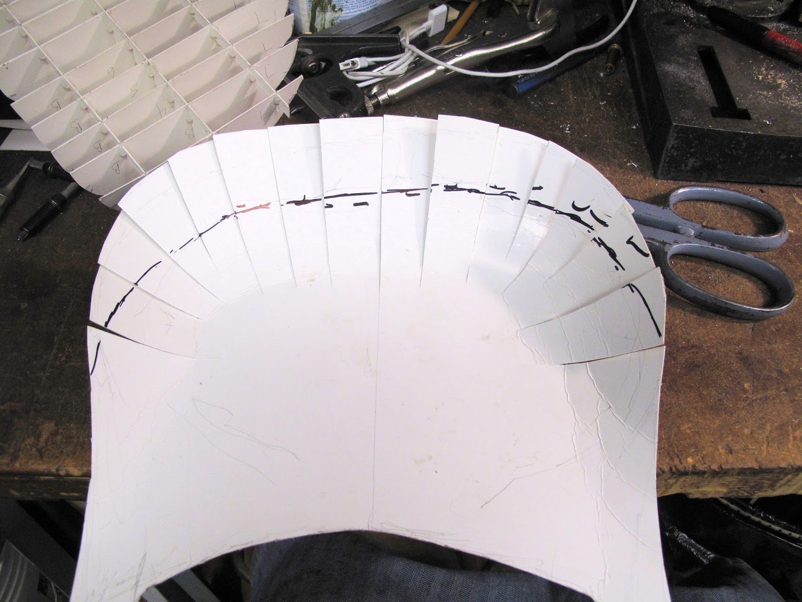
The black line is the edge of the aluminum.
I used a cutting board and a sharp knife to cut 1" slices.
The high side of each slice was traced onto card stock. Each piece was marked with centerline for re-alignment.
A cross cut was made along the centerline.
The pieces were slotted to allow assembly.
The result is a simple buck to use for checking the shape as a new piece is formed.
All the joints were glued with hot melt glue.
The pattern started with the top shape to fit the crankcase baffle.
The patterns was made oversize to be sure it would fit.
With the oversize pattern cut out, it was slit to allow the tabs to be bent to form the curved shape. Initially the tabs overlap each other.
It is also longer than needed to allow for a lip on the top for the screws.
The overlap get marked on each piece and trimmed to a tight fit. When the pattern is flattened these cuts form wedge shaped gaps. The tabs were also cut to length based on the final formed shape.
With all the tabs taped together you can see that the pattern forms the desired shape.
The wedges were drawn on the 3003 H14 aluminum blank and it was cut to shape.
The wedges represent how much and where the aluminum needs to be shrunk to for the curved shape.
You shrink the aluminum by creating little wedge shaped tents in the aluminum and the smashing them flat with a hammer. It forces the walls of the tent into the surrounding aluminum making it thicker.
The more vertical the walls the better it works to smash them flat. I used a piece of 0.070" aluminum with a rounded edge to form the tents.
I also increased the bend of the flat sections to help form the curves.
It looks like a metal beer bottle cap. We're just going to hammer out the wrinkles.
The tents get smashed flat leaving a scoop shaped piece. Because this is a baffle I'm not worried about smoothing it perfect.
If need be you could anneal the aluminum with a torch and shrink it more.
The baffle is installed between the carburetor and the oil sump.
Because it is soft aluminum it was easy to from a lip on the top edge for the screws, using a form block and rubber mallet.
A bracket was made to screw the bottom of the baffle to the back of the carburetor heat box.
Now we need seals to force the air to flow through all these baffles.