Monday, October 24, 2016

A Bucket Seat For Fly Baby


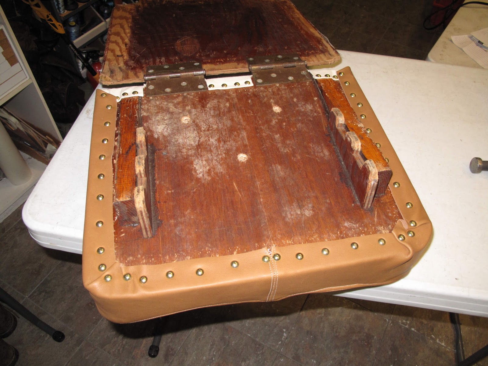
 The seat for Fly Baby is just 2 pieces of plywood.  It has two door hinges to join the pieces at the bottom so the seat bottom can be slid fore and aft while the top rests against the former at the back of the cockpit.  There are some pieces of wood on the bottom to control the angle of the seat and latch it in a couple different positions.  It's simple and it works.

It's real problem is setting on it for more than about 1/2 hour is painful.  Just padding it with a piece of foam rubber means you're sitting on 2 pressure points on your hip bone.  We had increased the foam to about 4" thick.  That makes you sit higher in the cockpit  but only gets you a few more minutes before the pain starts.

A bucket seat supports you on all that soft muscle tissue around the hip bone so you don't put pressure on the just the bottom of the hip bone.

My first effort was to put some wedges made from Ethafoam, that stiff white packing foam, on the sides of the seat to provide more support.  That improved the flying time to a couple hours.  You can still see the wedges in some of the pictures below.  For this project I'm just adding more support.
 My plan was to make a bucket seat using stiff foam that would fit my bottom to give the best support.  I bought a camping pad about 1/2" thick with the plan to cut pieces which I could stack up and glue together to form the bucket.

First I needed a pattern of the shape of my bottom sitting in the seat.  The idea was to fill a bag with canned urethane spray foam, sit on it, and let it harden.  Good plan, but it turns out it needs moisture to cure and therefore will not harden in a plastic bag.  I eventually did it using paper towel instead of a plastic bag.  I've lost the pictures and it was messier than the plastic bag, but I made a workable pattern.

 The next step was to draw contour lines on the pattern.  I started by putting a felt pen in the drill press chuck and drawing a line at the lowest level.  I then moved the chuck up by the thickness of my foam pad and drew the next line, etc.  You can see the Ethafoam wedge below the foam.

The result was a pattern for the final bucket seat.

 The plan view photo of the contour lines was brought up in TurboCAD and a printable pattern drawn to make the foam pad layers.

The pad layers were made from 3 pieces which overlap in the corners for strength.  That way I didn't even use up all of the one pad I bought.  The pieces were glued together and the the corners sanded off to make a nice fitting bucket.

 For the back I wanted to sit as far back as possible so again I wanted some support on the sides and the lumbar area.  I used Rowan's old foam rubber Noodle to make the supports, taped on here to check location before gluing them to the back.  To minimize the foam between them I used a piece of an old mattress pad, soft but not very thick when easily compressed.

 I wanted the bucket look hidden.  Instead I wanted the older look of a simple seat padded like the original Fly Baby seat.  I needed something to hold up the seat cover but which would not add much actual padding to disrupt all this structure I had created.  We had recently bought some cheap pillows with a polyester stuffing instead of feathers or foam.  The softest one I found at Walmart was labeled Medium Firmness.  I opened it and used some of the polyester stuffing to fill the bucket.

Once I had enough of the stuffing I used spray adhesive to glue it into the bucket.


 I then glued a piece of felt over this to hold it in the bucket over time.  The felt was glued to the top and sides of the bucket
 I found a soft cow hide on line for a cheap price and exactly the color I wanted.  Ah the joys of the modern internet.  It's hard to imagine that before the 90's we could loose our e-mail privileges if we did something as "Commercial" as to include a price quote in an e-mail.  They monitored the network looking for violations.

I made a pattern and sewed up the cover for the bottom I used canvas in the back because I thought it would hold up better and fit better around the hinges.

 I started attaching it at the back and worked forward.

I think this is the third seat cover tacked to our original seat.

 I'll never have a career covering seats but I like it.
 The back was done the same with a little of the polyester fill to puff it up as well.

The final seat ready to go back in the plane.  It's as comfortable as planned so I'm eager to get flying and see how it works on a long flight to Michigan and Oshkosh.

Sunday, October 23, 2016

Dad's Old Fly Baby Trailer


 On my way home from the Antique fly-in I stopped at my parents house and picked up the old Fly Baby trailer.  Dad had shortened it and added a box for his large scale RC models.  He's quit flying them so we removed the box, put on new tires and replaced the inner wheel bearings, water had leaked in.  It's now back here in Virginia.

I need to lengthen the tongue so I bought an old boat trailer for $200 and I'll combine the 2 trailers .  The plan right now is to use the boat trailer to create a long tongue for the Fly Baby trailer.  We'll see how all that works out.  I figure the boat trailer cost me less than the steel needed for the longer tongue.

Saturday, October 22, 2016

Rudder Pedal Back Stops and Rudder Cable Guides

While at the Antique Fly-in (Blakesburg) I spoke with a fellow who had flown a Fly Baby a few times but was now terrified of them.  While taking off on his last flight the return spring on a rudder pedal had broken.  This allowed the pedal to fall aft, toward him, on the floor.  The result was that he only had rudder on one side and the plane careened off the runway, stopping between two parked planes.  With the pedal on the floor there was no way to get it hooked with his heel to lift it back up. He missed the planes and only did minor damage to the Fly Baby, but wanted nothing more to do with Fly Babys.

I always wondered about the return spring but had assumed that if it broke my feet would be on the pedals and there would be no problem, bad assumption.  Without the return spring the rudder cable pulls it aft to fall on the floor. 

I mocked up a simple stop on the aft side for the pedal to fall against.  There is no load on the pedal except it's weight and the weight of the cable so I made them from 0.040" aluminum.

I Alodined the aluminum to to protect it and screwed the stops to the floor.  With the pedals reinstalled they stop at about a 60 degree angle aft.  This is as far aft as the return spring normally allows.

We used some old CUB rudder pedals but this idea would work with the standard pedals.


The rudder cables were slowly sawing through the plywood gussets in the corners of the cockpit bulkheads.  Originally my plan was to use CUB split nylon cable guides.  I filed out the holes to make room for the guides and then ran the new rudder cables.  Unfortunately the CUB guides are only 3/4" long and the bulkhead is 1" thick.  I didn't want to remake the cables so I needed something which could be installed like the CUB guides.
I thought of machining some longer guides but really didn't want to go to all that trouble.  Instead I found some 1/2" and 5/8" nylon tubing connectors at the hardware store and Tractor Supply.  When I filed out the holes I didn't make them all the same size, for whatever reason, so the 5/8" fit 2 of the holes and the 1/2" fit the other 2 holes.  I could have filed out the holes but I was worried about nicking the cable with the file.

To install the guides I split them on one side with an Exacto saw.  This allowed me to pry the split open to slip it over the cable.
With the split on the opposite side from where the cable rubs, I safety wired the guide to the bulkhead.  The barbs on the coupling make nice grooves for the safety wire so the guide won't slide fore and aft with cable motion.

On the first one I used 0.040" safety wire.  This was hard to work with so I used 0.032" wire for the rest.  I think I got the wire tighter with the smaller wire.

If these wear out I can easily replace them.


Monday, August 15, 2016

Welding The New Gas Tank


 The first step was to nibble away the flange on the end plates between the Cleco tabs.  My first plan was to nibble with the outside of the flange up so I could easily see what I was doing.  The nibbler would stop against the plate to control how much of the flange was left for welding.

I cut little notches and then cleaned them up.  The Clecos act as stops to assure I don't cut off the tabs.


 It worked fine and left just the amount of flange I wanted for welding, just to the edge of the radius.  The idea is to make an easy fusion weld and the penetration behind the weld would fill the corner making it easy to clean up any flux inside the tank to prevent future corrosion.  A corner weld should also make the bending loads on the weld joint less than at the end of the 1/2" flange.

The problem I found was that the chips come out the bottom of the nibbler and scratched the end plate as it rubbed against the nibbler, bad plan.

 I made a new end plate in about 45 minutes.  I'm getting too good at this.

I'll nibble this with the outside of the flange down this time so the chips are free to fall.  I also put strips of Gorilla tape along the radius to protect it and to control the depth of the nibble.

Again the Clecos act as stops for the tabs.


 It was a little more awkward to do this but it worked.  I first did the perpendicular cuts as I did previously.  It worked but it was slow.  I have a lot of notches on the flanges and then on the skin.

 Next I tried cutting notches at each end and then driving the nibbler along the plate.  I couldn't make it work well.

 Next I tried the same end cuts and then just a sideways motion using the back of the nibbler as a guide along the edge of the aluminum.  It took 3 passes and it was done, and they went quick.

It did take some practice to hold the edge touching the nibbler housing to make a nice straight cut.

In the end this was how I did the remaining cuts.


 Once the notches were cut I cleaned up the corners around the Clecos to reduce the chances of cutting myself on a sharp corner.  It did work, I never cut myself.

The edges and tabs came out well.

  I then assembled the end plates on the skin and used the end plate as a stop for the skin notches.  It was much more awkward to do this with the whole tank in hand but it worked.  It doesn't cut as deep because the cut edge of the end plate hits the housing of the nibbler.  It's a small difference, about 0.020", and my experiments say it should not cause a problem welding.

Again I cleaned up the tabs on the skin just like the end plates.

 The top seam was done the same way and everything is Clecoed back together ready to tack weld.  So far the plan is working.

 There are 2 or 3 tack weld between every tab.  I found that a tack every 1/2" - 3/4" was needed or the skin will pucker out creating a slight gap when the torch heats it.  Oh yeah, I'm Oxy-Acetylene welding the tank.


 Some of the things I've learned Oxy-Acetylene welding 0.040" Aluminum are:
- You only need to flux the edges of the assembled parts to weld,
- It's easier to weld aluminum that is fit very tight, the aluminum is thin and gaps lead to holes, even more so when you are trying to fusion weld a corner,
- You can almost gas weld steel in the dark because it makes so much light, You need bright light at the weld for Aluminum,
- Use the biggest tip you can control, you want to minimize the size of the heat affected zone to prevent holes forming, if the metal doesn't quickly puddle you are using to small a tip,
- The rod can be used as a heat sink and to stir metal to get it to flow together,
- With these 2 pieces of sheet aluminum at 90 degrees to each other start the torch at the outer edge, flame parallel to the outer skin, it will take more heat to get the outer skin to flow than the piece which is perpendicular to the flame, which will easily heat enough to make a hole,
- If a gap opens either stop and hammer it shut, or quickly get the rod into the puddle to cool it while you use the rod to run the bead in the area of the gap, then you can go back to doing the fusion weld.
- If a hole opens get out of there and let it cool, work your fill puddle in steps around the edges,
- If the weld is not smooth and well bonded it might be strong enough but it will leak.

 The tabs were easily cut off with the snips leaving a nice tight spot for a tack weld.


 A nice looking section of welding.

While washing and scrubbing the inside of the tank to get rid of the flux I found a few leaks where the water sprayed through.  Those were a quick fix.

 I then used Gorilla tape to seal the access panel.  I also had some tape on the inside which the air pressure blew down tight.  I found before that the blower end of my vacuum will only put out 2 psi so it's a quick way to pressurize the tank.  Put a pressure gauge, or water manometer, on the outlet of the tank and use a dimmer control on the vacuum to slowly bring it up to pressure.

Bubble solution quickly finds small leaks.  I still plan to pressurize the tank and let it set to see if there are any leaks so small I missed them with the bubbles.  You can't do that with the vacuum blowing.

 With the leaks fixed the tank was treated with Alodine to give a little better corrosion protection and the access panel was screwed on.

I applied sealant around the screws and with 2 beads between them.
I started the assembly with 4 screws in position through the clamp ring and carefully started them before starting all the others. I didn't want the sealant smeared, just compressed to make a good seal.  Once all the screws were started I put some more sealant under the edge of the tank opening.  With the screws tightened I used the round end of a craft stick to clean up the sealant.


 The front and back of the finished tank.  The weld on the forward seam is the best and it's the one I did first.  I had a lot of gaps open on the aft seam.  I eventually figured out that if I kept the rod close and in motion, even though I didn't use it in the fusion weld, I could more quickly get it into the puddle at the start of a gap, if it formed, and keep on welding.  The gaps this worked for were only about 0.010".  When the gap opened you suddenly had a small puddle going on the edge of each piece but not enough metal to bridge the gap without getting the rod quickly in the puddle.  Any hesitation and the skin, being perpendicular to the flame, would form a hole.

 The square bottom and tapered top of the tank can be seen here.

The outlet fitting turned out to be easy to weld.  The small welding lip on it fused easily with the flange on the tank.

 In the fuselage setting on the supports.  I need to make the straps which will hold it in place.

 There are some bolts in the front which limit how far forward the tank can go as well as the forward struts of the Cabanes.

The straight edge shows the cowling line.  It looks like the filler will be out of the cowling.  I may need a slight bump in the cowl.  Once the tank is strapped in place I can put the filler neck hole in the cowling and work out any bump needed.