Wednesday, October 21, 2020

A longer Test Flight

 Today was another nice warm day with a light breeze out of the southwest.  I flew about 20 minutes.  The motor was still running hot, 450 Deg. F.  I flew around the pattern until the oil temp. got close to red line, then landed.  When I went to pull carb heat I found I had been flying with it on heat.  I think what happened was I was going to land on the first pass around because of the temp. and pulled carb heat on downwind, then changed my mind and kept going around, forgetting to move back to cold air.  I'll probably give it another go tomorrow.


My landing was better.


I took this video on on pass around the pattern  It starts toward the end of the downwind for 23.  It ends after turning to base, toward the mountain.  Just at the end you can see Gordonsville airport between the left wings.  The mountains way in the back are the Blue Ridge.  It was a nice afternoon.


Sunday, October 18, 2020

New Felt Seals for the Motor's Main Air Cooling Baffle

 I think I've improved the seals on the main air baffle.

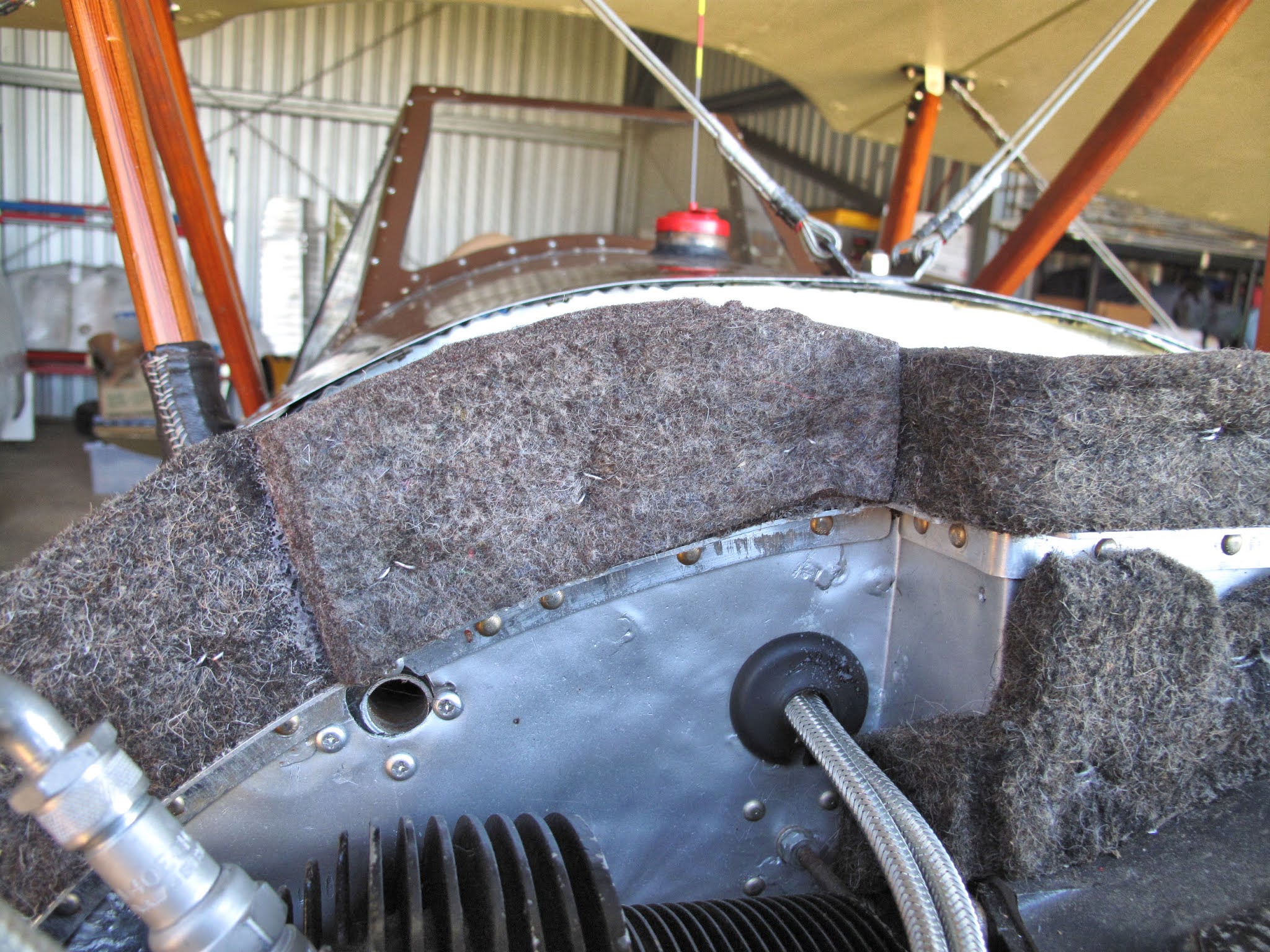
The center section of the seal seams to fit just fine.  The pressure of the cowl pushing down on it forces the felt to tip forward toward.  This should help the air pressure to hold it tight against the cowl.

Therefore I cut that section out from the long seal and reinstalled it.
There is clearly a leak on both sides along the cowl doors.  I stuck "T" pins in the edge of the felt so I could determine where and how big the gap really is.

The doors were fastened shut to push the pins into the felt.

With the light behind the seal I could see that the pins were not pressed too far down.


This gave me a pretty good idea where and how much the seals needed to be widened to get a good seal like in the center.


I cut new pieces and this time I used some spray adhesive to bond the felt to the aluminum, in addition to the staples.  I masked everything to keep the spray only on the baffle.

The new sections are quite  bit taller than the old ones so I trimmed them with the scissors to make a smooth blend.

I also used the scissors to put about a 30 degree chamfer on the aft edge to make it more flexible.  I left the top edge about 1/8" wide and ran the chamfer down the back about 3/4" - 1".  The idea was that this tapered section would tip forward and seal better against the cowl doors.


I made more new staples from 0.041" stainless safety wire, as before, to secure the felt to the baffle.

When I got it all done I found I had a slight gap at the piano hinge for the doors.  I split some felt to about 3/16" thick to make patches for each side.  I glued these to the main pieces and redid the staples, again.


These patches fold over nicely under the hinges and should seal very well.
I also widened the pieces under the rocker covers, on each side.  I had previously moved them outboard, but I don't think they were sealing good enough.  Now they really press against the cowl.


I like how these came out, but I need to fly the plane to see if the cooling problem is solved.  

We have a week of warm sunny weather coming so hopefully that will happen soon.


Tuesday, October 13, 2020

Cooling Air Leak and Ignition Shut-Off Problem

 One of my tasks after the test flight was to re-inspect the plane and particularly the motor to make sure nothing is loose, leaking, etc. as well as making sure once again that everything is properly safetied.  I haven't found any problems, which is good.

Before taking the cowl off I had a bright idea, I should have had ages ago, to put a light behind the main cooling air baffle so I could see if there were any air leaks.  It turns out the cowl doors do not seat against the felt seal on the baffle.

That sliver of a gap is about 3/8" wide in the middle and 12" long.  I have ideas for fixing it.  We'll get back to it in another post.

With the cowl off and the top spark plugs out for safety, I checked the mag. switch wiring with an Ohm meter, but couldn't find a problem.
I decided to remove the mag. switch to see if it was malfunctioning.  Fortunately it's serviceable.  By removing the 2 screws you can remove the back plate.
The fixed contacts look real good and still have grease to prevent corrosion.

The movable contacts bridge from the center, ground, to the outer, magneto, contacts.  They're in good condition also.

The movable contacts are held in place by the springs, which are the same length with no broken coils.


There are detent bumps on the moveable plate, attached to the key tumbler, which hold the switch in each position.

The detent spring is OK and works well.

Overall the switch is not the problem.  I've reassembled and reinstalled it.
Before hooking up the switch I used the magneto timing light to make sure there isn't an open in the magneto's internal wiring by rechecking the point timing.  No problem there.

While reconnecting the switch wiring to the magnetos I found the problem.  The wire on the left magneto had broken at the screw terminal.  I had put a piece of heat shrink tubing over the wire and the end of the terminal as a strain relief.  The idea was to stop motor vibration from wiggling and breaking the wire at the end of the terminal. That was a good plan but, with all the removing and reinstalling of the magnetos I wiggled and broke the wire.  Trapped under the heat shrink tubing it wasn't obvious it was broke.  while holding the meter probe to it for good contact the broken wire made contact, hiding the problem.  I've installed a new terminal, without the tubing.

We'll find out for sure I've solved the problem once I've finished with the baffle leak.  Until then I'll treat it as a hot engine, top plugs out when working around it.


Friday, October 9, 2020

Successful Test Flight


We finally have a day with the wind out of the south at about 7 knots on a warm comfortable day.  I wanted to use runway 23 (to the southwest) for the best emergency landing fields, and the runway is uphill in that direction if an abort was needed, much better than going down hill.

One more thorough preflight inspection just incase I've missed something.  

The plan was to do the normal run up checks then on take-off check that the plane is not wildly out of rig, if yes abort take off.  If that's fine climb in the pattern to 3,000 feet and stay over the airport getting familiar with the plane in normal and slow flight.  The slow flight was intended to understand the airplane and see what the airspeed indicator reads for landing.  There was no plan to do stalls at this point though.

The motor is running and it's time to get started.


Everything checked ok during run-up so were ready to fly.

I was a little jerky on the rudder pedals just before take off and I considered aborting but by then I was off the ground.  The plane flew nice with a light grip on the stick.  The rigging was good so on with the flight.


By the time I was at pattern altitude the cylinder head temperature was at 450 degrees F.  I throttled back to 2,300 RPM and the temp. dropped back down a few degrees and stabilized.  I decided to stay in the pattern at 1,000 feet AGL.  In this picture I'm in the up-wind.  

Any change in speed or power caused the temp. to go up so I decided to come on around and land without any slow flight practice.
In this picture I'm in the down-wind to land back on 23.  I'm sure the Airspeed Indicator has an issue because at one point I was up to 100 MPH, in the downwind.  This Fly Baby has never gone that fast before.  We'll check it out more on the next flight.
On short final the plane started settling very fast and I was slow getting the throttle up enough, One Good Bounce For Mankind.  I got the throttle in on the bounce and with almost all the runway left decided to land.  This time I made a much better landing.  Yay!!!


I discovered another small problem when I got back to the hangar.  The ignition switch wouldn't shut the mags off.  It worked fine every time I taxied the plane.  I shut off the gas and waited a minute or 2 for it to shut down.  We seem to have a weak ground from the switch so I'll probably replace the switch.  

I have some ideas where I may have cooling air leaks so we'll see how that works out.

A good productive day all around!


Monday, October 5, 2020

Brake Dragging Slightly


The left wheel is back off because there was a light drag in one spot.  It was there when I put on the new bladder.  I decided to taxi it a bit and then see if it was still there, of course it was.  It hung up the wheel enough I was worried it would do something squirrely when the wheel started turning on landing.  The right thing to do was to pull it back apart and fix it.
It happened in one spot as the wheel turned so I assume the 70+ year old brake drum is slightly out-of-round as well as something out-of-round with the mechanism.  
First I blued the metal frame thinking it was rubbing, based on the sound.  That wasn't it.

I used the blue marker to blue the entire inside of the drum.  Spinning the wheel rubbed plenty of blue onto 2 of the pads.  I measured those 2 pads and found they were 0.300" thick, basically new.  I sorted through the pads I have and found 2 which were worn  about 0.010" thinner.  That solved the stopping on the pads, but now I could for sure hear metal on metal wear.
I removed the pads and blued the metal frame that holds the pads in position, wheel back on and spin.

With the pads removed there were areas where the blue was rubbed off the frame.  After 4 hours filing a little, cleaning up metal filings, re-bluing, installing the wheel, spinning, removing the wheel and repeat, I stopped the metal rubbing.

The wheel spins great and the brakes are ready for a test flight.

I need the wind to switch back to a southerly wind and we're ready to fly.  Yay!


Friday, September 25, 2020

Had Held Thermocouple Thermometer - $24


While looking for a cylinder head gauge, that is in stock, I found this Thermocouple Thermometer for $24 with tax and free shipping.  It's made by Leaton (model 1312) and has sockets for 2 thermocouples.  It's about the same size and weighs about the same as my digital multi-meter.  It's just a thermometer which works with 7 different thermocouples, including types T and J which I have.  It has a backlit display, 30 seconds, but is easy to read with the light off.  If you hold down the Hold button as it powers up it won't power down unless you push the power button.  It comes with 2 type K thermocouples which plug into the top.  When you power it up, it comes up for whatever type thermocouple you used last.
I ordered some type T and Type J blade type connectors from McMaster Carr.  They were less than $4 each plus postage.  The little red gasket is to seal the wire and grip it.

They come in colors for the type thermocouple they work with.  They are also easy to assemble.

The amazing thing was that all the way to 445 degrees F, as hot as my hot plate would heat the oil, it agreed with my other thermometers within 1 degree.  Who could ask for more for $24.  It fits right where I had the multi-meter.

I've added a label with the temperatures, green arc 300-460, red line 540 degrees F.

I think we're about ready to go flying.


Monday, September 21, 2020

Cylinder Head and Oil Temperature Gauge Problems

 While Taxiing the plane I didn't have any reading on the Cylinder Head gauge nor the Oil Temperature gauge.  It turns out both gauges are dead.  Despite the fact that everything worked when I took the plane apart I should have checked all the gauges before putting them back in.  Only the oil pressure and tachometer seem to work correctly, even the clock is dead.

The cylinder head temperature gauge is WWII surplus, so no shock it's quit working.  It was built by The Lewis Eng. Co. P/N 17AT4P.  

It uses a thermocouple to measure the temperature.  On the back it says to "Use 2 Ohm CC Leads".  The large nut is marked "+" and the small one "-".  

OK, what's all that mean?

After 3 books on instruments and several web sites I think I've got it.  A thermocouple is made by joining 2 wires of different metals.  When that junction is heated it produces a voltage which is measured by the gauge.  The gauge is basically a voltmeter marked in units of temperature instead of volts.  There are about 8 common combinations of wire used to make thermocouples.  The website thermocoupleinfo.com has lots of explanations and data to help select an appropriate thermocouple.

The gauge also has a thermocouple in it, made of the same wires, so that it compensates for ambient temperature.  It's really measuring the difference between the 2 thermocouples so the positive (+) and negative (-) leads need to be connected to the correct terminal for the gauge to read the head temperature correctly.  There is an adjustment screw on the front of the Lewis gauge.  You're not adjusting the pointer to zero but to the ambient temperature.  Once set it doesn't require regular adjustment.

There are 2 common thermocouples types used for aircraft cylinder head temperature.  The first is Type J which is made with an Iron wire and a wire made of Constantan.  

Here we go again, what on earth is Constantan.  It's a wire made mostly from 2 metals, Nickel (about 45%) and Copper (about 55%), and bits of some others.  Constantan gets it's name from the fact that it's Electrical Resistance is Constant (doesn't very much) as the temperature changes.  Because of this property, it is used to make Strain Gauges, for measuring forces acting on structural parts.  I would love to digress on strain gauges but not now.

Back to our Type J thermocouple.  It needs a gauge with the internal thermocouple made with Iron and Constantan.  The back of the Lewis Iron-Constantan gauges are marked "IC Leads".  The Iron lead is the Positive (+) and Constantan is the Negative lead (-).  The old Style 18mm spark plug J Type thermocouples have Black Insulation on the Iron Lead and White on the Constantan lead.  You can also check to see if a magnet sticks to the iron lead.  Modern Type J wire has White Insulation on the Iron lead and Red on the Constantan.

Here's some of the information from Thermocouples.com.

The other common cylinder head thermocouple is a T Type.  They are made with a Copper wire and a Constantan Wire.  The back of the Lewis Copper-Constantan gauges, like mine, are marked "CC Leads".  The Copper lead is the Positive (+) and Constantan is the Negative lead (-).  The old Style 18mm spark plug T Type thermocouples have Red Insulation on the Copper Lead and White on the Constantan lead.  A magnet will not stick to the copper lead.  Modern Type T wire has Blue Insulation on the Copper lead and Red on the Constantan.

Iron-Constantan thermocouples generate a little more voltage than Copper-Constantan, at the same temperature.  Iron can also go to much higher temperatures, but both can go well above the maximum cylinder head temperature, 540 Degrees F for my C-85.

For the gauge to read correctly the important voltage is what is available at the gauge.  The rĂ©sistance of the lead wires reduces the voltage generated at the thermocouple by the time it gets to the gauge.  The longer the wires the lower the voltage at the gauge.  So how long should the leads be to read the temperature correctly?  The answer is on the back of the gauge, "Use 2 Ohm CC Leads".  If the leads have 2 Ohms of resistance the Lewis gauge will read correctly.  The trick then is to cut the leads to length so they have precisely 2 Ohms of resistance.


The old Lewis gauge is dead so I've temporally made use of my Digital Multimeter as a temperature gauge.  It has a temperature function.  As it turns out it uses a Copper-Constantan thermocouple (Blue/Red wires).  I don't want to mess with the length of the leads for a temporary solution so I decided to just calibrate what I have so I'll know what reading keeps the head temperature within limits.
I started by using Boiling Water, on my little hot plate.  Water boils at 212 degrees F.  The meter is reading 218 degrees F.


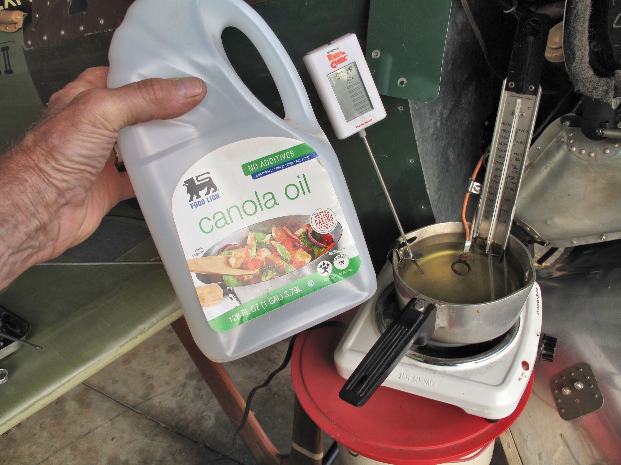
To get to higher temperatures I'm using Canola Oil which can easily go to the limits of my candy thermometers, 400 Degrees F.

With the oil at 332 Degrees F the meter reads 362 Degrees F.


I've pushed the oil up to 410 Degrees F and the meter reads 458 Degrees F.

I've plotted the data.  If I keep the meter between 310 and 500 Degrees F I'll be in the normal operating range of 300 - 460 Degrees F.

I made up some short leads to connect the existing leads to the meter, before I did my testing.  The meter is very light so I've attached it to the big turnbuckle with some double sided Velcro.

I taxied around with it and it works fine, easy to read.

My next task was the Oil Temperature gauge.  I ordered a new Rochester gauge from Spruce.  I checked it's calibration with boiling water.  It reads about 10 Degrees F low so I'll put the red line at 210 Degrees instead of the 220 Degrees F listed in the manual.

This gauge uses a Bourdon Tube pressure gauge marked to read temperature.  The tube is a curved thin copper tube which moves to uncoil as pressure is increased.  This pulls the link which moves the sector gear, turning the pointer.

For a temperature gauge the pressure source is a sealed tube, capillary, filled with something like Methyl Chloride.  As the bulb at the end of the tube gets heated, in this case by hot motor oil, the fluid expands causing the pressure to move the needle.


The hard part was getting the old gauge out and the new gauge in.  I had to remove the cowl panel with the windshield riveted to it.  The last time I did this I took off the wing center section.  I was not interested in taking off the wings.  A lot of careful wiggling and I managed to remove it.

I had wrapped the primer lines, ignition wires and the gauge's capillary tube with friction tape and then securely clamped this group to the wooden tank support.  The rear clamp was just aft of the tank, and fairly easy to unscrew.  The forward clamp is just under the tank above the rudder pedal.  I had to lay down in the fuselage, remove the clamps and friction tape, and then get back out to remove the gauge.  It took a very short screw driver, and many tries, to get the bottom screw removed so the clamp could be pried up enough to remove the bundle.  I should have put that clamp forward of the tank.


Before I installed the new gauge I put some white electrical tape on the capillary to mark where the friction tape would wrap everything, using the old tube as a guide.

It took some wiggling to snake the new capillary tube in the right place and then through the hole in the firewall.  Once I was sure it was routed correctly I clamped the new gauge in the panel, so it would be rotated to the right position.  Then I coiled up the excess tubing and screwed the bulb into the adapter on the back of the oil screen, on the motor.

Then back into the fuselage with some new friction tape to re-wrap everything and re-screw the clamps.  The whole process went well but took a couple hours.

The new gauge is in and marked.  I've now got the cowl back together and will do some taxiing, to check that it all works.  

We're getting close to flying.  Yeah!!